Table of Contents
Advertisement
Quick Links
Surface Scatter
General information
Safety information
Use of hazard information
®
7 Auto Flush Kit
In no event will the manufacturer be liable for direct, indirect, special, incidental or
consequential damages resulting from any defect or omission in this manual. The
manufacturer reserves the right to make changes in this manual and the products it
describes at any time, without notice or obligation. Revised editions are found on the
manufacturer's website.
The manufacturer is not responsible for any damages due to misapplication or misuse of this
product including, without limitation, direct, incidental and consequential damages, and disclaims
such damages to the full extent permitted under applicable law. The user is solely responsible to
identify critical application risks and install appropriate mechanisms to protect processes during a
possible equipment malfunction.
Please read this entire manual before unpacking, setting up or operating this equipment.
Pay attention to all danger and caution statements. Failure to do so could result in serious
injury to the operator or damage to the equipment.
Make sure that the protection provided by this equipment is not impaired. Do not use or
install this equipment in any manner other than that specified in this manual.
Indicates a potentially or imminently hazardous situation which, if not avoided, will result in death
or serious injury.
Indicates a potentially or imminently hazardous situation which, if not avoided, could result in
death or serious injury.
Indicates a potentially hazardous situation that may result in minor or moderate injury.
Indicates a situation which, if not avoided, may cause damage to the instrument. Information that
requires special emphasis.
N O T I C E
D A N G E R
W A R N I N G
C A U T I O N
N O T I C E
DOC273.53.80483
1
Advertisement
Table of Contents

Related Manuals for Hach Surface Scatter 7


Summary of Contents for Hach Surface Scatter 7
- Page 1 DOC273.53.80483 ® Surface Scatter 7 Auto Flush Kit General information In no event will the manufacturer be liable for direct, indirect, special, incidental or consequential damages resulting from any defect or omission in this manual. The manufacturer reserves the right to make changes in this manual and the products it describes at any time, without notice or obligation.
-
Page 2: Specifications
Precautionary labels Read all labels and tags attached to the instrument. Personal injury or damage to the instrument could occur if not observed. A symbol on the instrument is referenced in the manual with a precautionary statement. This symbol, if noted on the instrument, references the instruction manual for operation and/or safety information. This symbol indicates that a risk of electrical shock and/or electrocution exists. -
Page 3: Installation
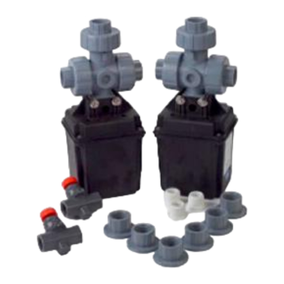
Figure 1 Product components 1 Solenoid valves, 3-way, with fittings for glued connections 3 Flow control valves, ½-inch NPT PVC (2x) (2x) 2 Replacement fittings for threaded pipe connections (6x) 4 Reducer bushings, ¾-inch MPT x ½-inch FPT (3x) Installation D A N G E R Multiple hazards. - Page 4 Connect to a relay D A N G E R Electrocution hazard. Always remove power to the instrument before making electrical connections. D A N G E R Fire hazard. Do not daisy-chain the common relay connections or jumper wire from the mains power connection inside the instrument.
- Page 5 Figure 2 Wiring overview 1 Solenoid valve for cooling water/flush water inlet 4 Neutral line (–) 2 sc200 controller 5 Solenoid valve for sample inlet 3 Power line (+)
- Page 6 Plumbing Make the plumbing connections that are shown in Figure 3. The pipe, adapters and tee fittings are supplied by the user. Notes: • The valve location and orientation is not important. Figure 3 shows an example installation. • The flow control valve fittings are ½-inch NPT. •...
- Page 7 Figure 3 Plumbing connections 1 Cooling water/Flush water inlet 8 Outlet to turbidimeter 2 Heat exchanger 9 Flow control valve, ½-inch NPT PVC 3 Cooling water/Flush water to drain 10 Sample to turbidimeter 4 Solenoid valve for cooling water/flush water inlet 11 Sample inlet 5 Bubble trap 12 Sample to drain...
- Page 8 Configuration Set the flush frequency and cycle time Configure the sc controller to close the NO (normally open) contact of the relay on a schedule. When the NO (normally open) relay contact closes, power is supplied to the solenoid valves and the water flow direction changes from normal flow to flush flow. Refer to Figure 3 on page 7 for the normal flow pathway and the flush flow pathway.
-
Page 9: Set The Flow Rate
Figure 4 Relay function 1 Duration 3 Interval 2 Off delay 4 Time (x-axis) Set the flow rate 1. Push MENU. 2. Select Test/Maint>Test Relay>Energize to do a flush. 3. Slowly open the flow control valve to set the flow rate for the auto flush. Refer to Figure 3 on page 7. - Page 10 SWITZERLAND Fax (970) 669-2932 Fax +49 (0) 2 11 52 88-210 Tel. +41 22 594 6400 orders@hach.com info@hach-lange.de Fax +41 22 594 6499 www.hach.com www.hach-lange.de © Hach Company/Hach Lange GmbH, 2014. All rights reserved. Printed in U.S.A. 06/2014, Edition 1...
Need help?
Do you have a question about the Surface Scatter 7 and is the answer not in the manual?
Questions and answers