Table of Contents
Advertisement
Quick Links
OPERATING INSTRUCTIONS
230V 50HZ
IGBT
DIRECT
CONSTANT
SINGLE
INVERTER
CURRENT
CURRENT/
PHASE
TECHNOLOGY
OUTPUT
VOLTAGE
ADVANCEMIG 255C
MULTI-PROCESS MIG WELDER
LIFT TIG
SPOOL GUN
POWER
(OPTIONAL
CAPABLE
FACTOR
TORCH)
CORRECTION
www.strata.co.nz
LCD
IP23 CORROSION
SPIKE/
INTELLIGENT
SCREEN
& SALT SPRAY
GENERATOR
PROTECTION
RESISTANT
SAFE
SYSTEM
MULTI-VOLTAGE
SYNERGIC
VOLTAGE
INPUT POWER
OPERATION
REDUCTION
DEVICE
Advertisement
Table of Contents
Troubleshooting

Related Manuals for Strata ADVANCEMIG 255C


Summary of Contents for Strata ADVANCEMIG 255C
- Page 1 ADVANCEMIG 255C MULTI-PROCESS MIG WELDER OPERATING INSTRUCTIONS LIFT TIG 230V 50HZ IGBT DIRECT CONSTANT SPOOL GUN POWER MULTI-VOLTAGE SYNERGIC IP23 CORROSION VOLTAGE SPIKE/ INTELLIGENT (OPTIONAL SINGLE INVERTER CURRENT CURRENT/ CAPABLE FACTOR INPUT POWER OPERATION SCREEN & SALT SPRAY REDUCTION GENERATOR...
-
Page 2: Table Of Contents
ADVANCEMIG 255C CONTENTS 1 Panel Functions & Descriptions ..........6 1.1 Machine Layout Description ..................6 2 Overview ..................8 2.1 Brief Intro duction ...................... 8 2.2 Technical Data ......................9 2.3 Duty cycle and Over-heat ................... 9 2.4 Working Principle ...................... 10 2.5 V olt-Ampere Characteristic .................. - Page 3 ADVANCEMIG 255C 3.3 Installation & Operation for TIG Welding ............. 45 3.3.1 Set up installation for TIG Welding ................. 45 3.3.2 Operation of the TIG Lift welding method ..............46 3.3.3 DC TIG Welding ........................ 49 3.3.4 TIG Welding Fusion Technique ..................50 3.3.5 Tungsten Electrodes ......................
- Page 4 ADVANCEMIG 255C Congratulations on the purchase of your new Stata Welding Product! The Strata range of Welding Products from Euroquip utilises the latest design technology and is engineered to produce welding products that combine market leading value, features and durability.
- Page 5 • ADVANCEMIG 255C • With IGBT and PFC technology the ADVANCEMIG 255C is a multi-process welder suited to a range of jobs and to 440V and IP23 protection mean this machine is built to withstand the harshest of environments found in the NZ workplace.
- Page 6 TIG Torch Pro-Grip 26 X 25Ft, Tgc End (Large Dinse) M12,(needs correct plug to be fitted ) Spool Gun 18004 SP100N Spool Gun 8m, suits Strata AdvanceMig Models (needs correct plug to be fitted ) MMA Consumables AAL3550 Arc Lead 25mm2 cable, 35-70mm plug, 4m 300A Twist-lock Electrode holder...
-
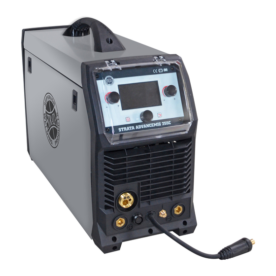
Page 7: Panel Functions & Descriptions
ADVANCEMIG 255C 1 Panel Functions & Descriptions 1.1 Machine Layout Description Front and rear panel layout of welding machine 1. MIG torch euro connector. 2. Positive (+) welding power output connection socket. 3. TIG torch gas connector. 4. MIG Torch Polarity Change Power Connection. -
Page 8: Overview
ADVANCEMIG 255C 2 Overview 2.1 Brief Introduction MIG series of welding machines adopts the latest Pulse Width Modulation (PWM) technology and the Insulated Gate Bipolar Transistor (IGBT) power modules. It uses switching frequencies in the 20KHz-50KHz range so as to replace the traditional line-frequency transformer type welding machines. -
Page 9: Technical Data
ADVANCEMIG 255C 2.2 Technical Data Model ADVANCEMIG 255C Parameters Input Voltage(V) 1~220/230/240±10% Input Current(A) Input Power(KW) Welding Current(A) 25-250 10~250 Welding Voltage(V) 10-30 (MIG) No-load Voltage(V) 67 (MIG) 14.5 (TIG/MMA) Power Factor 0.99 16% @ 250A Duty cycle 60% @195A Fe:0.6,0.9,1.0 Ss:0.8,0.9,1.0... -
Page 10: Working Principle
ADVANCEMIG 255C 2.4 Working Principle The working principle of MIG series welding machine is shown as the following figure. Single-phase 110V/220V work frequency AC is rectified into DC, then is converted to medium frequency AC by inverter device (IGBT), after reducing voltage by medium transformer (the main transformer) and rectifying by medium frequency rectifier (fast recovery diodes), and is outputted by inductance filtering. -
Page 11: Control Panel Of Welding Machine
ADVANCEMIG 255C 2.6 Control Panel of welding machine Main Start-up Interface Knob Knob 1. Function selection interface: rotate L Knob in the interface to choose from the four welding methods of MIG/MAG Synergic, MIG/MAG Manual, Stick and TIG Lift. 2. Synergic parameter selection interface: a synergic parameter may be selected by rotating L Knob in the interface. - Page 12 ADVANCEMIG 255C 5. Function icon display interface: an interface displaying the icon of the welding method currently used. 6. Welding mode icon display interface: an interface displaying the icon of the welding mode currently used (2T/4T). 7. Synergic parameter display interface: an interface displaying the synergic parameters currently used (only available when MIG/MAG Synergic welding method is selected).
-
Page 13: Installation & Operation
ADVANCEMIG 255C 3 Installation & Operation 3.1 Installation & Operation for MIG Welding 3.1.1 Set up installation for MIG/MAG Welding (1) Insert the earth cable plug into the negative socket on the front of the machine and tighten it. (2) Plug the welding torch into the MIG torch connection socket on the front panel and tighten IMPORTANT : When connecting the torch be sure to tighten the connection. - Page 14 ADVANCEMIG 255C (7) Place the Wire Spool onto the Spool Holder. Snip the wire from the spool being sure to hold the wire to prevent rapid uncoiling. Feed the wire into the wire feeder inlet guide tube through to the drive roller.
-
Page 15: Operation Of Mig/Mag Synergic Welding Method
ADVANCEMIG 255C (11) Pull the trigger to feed the wire through to the torch neck, release the trigger when the wire exits the torch neck. (12) Fit the correct sized contact tip and feed the wire through it, screw the contact tip into the tip holder of the torch head and nip it up tightly. - Page 16 ADVANCEMIG 255C 2. Selection of synergic parameters: 1) In the main interface, press the MENU key to enter the synergic parameter selection interface; 2) In the synergic parameter selection interface, rotate L Knob to select the required synergic parameters and press it for confirmation in the interface shown below: 3.
-
Page 17: Operation Of The Mig/Mag Manual Welding Method
ADVANCEMIG 255C 2) In the welding interface, rotate L Knob to set the welding current, for which the adjustable scope is different with the welding wires and gases; 3) The welding voltage will be automatically set as the value corresponding to that of the welding current set by rotating L Knob. -
Page 18: Wire Feed Roller Selection
ADVANCEMIG 255C 2) In the welding interface, rotate L Knob to set the wire feed rate and rotate R Knob to set the welding current; 3) After the settings, press L Knob and R Knob for confirmation; 3.1.4 Wire Feed Roller Selection The importance of smooth consistent wire feeding during MIG welding cannot be emphasized enough. -
Page 19: Wire Installation And Set Up Guide
ADVANCEMIG 255C Flux Core / Gasless Wire - these wires are made up of a thin metal sheath that has fluxig and metal compounds layered onto it and then rolled into a cylinder to form the finished wire. The wire cannot take too much pressure from the top roller as it can be crushed and deformed if too much pressure is applied. - Page 20 ADVANCEMIG 255C (3) Fit the wire spool onto the spool holder (4) Snip the wire carefully, be sure to hold fitting the locating pin into the location holeon the wire to prevent the spool uncoiling. the spool. Replace the spool retaining nut tightly.
- Page 21 ADVANCEMIG 255C (8) A simple check for the correct drive tension is to bend the end of the wire over hold it about 100mm from your hand and let it run into your hand, it should coil round in your hand without stopping and slipping at the drive rollers, increase the tension if it slips.
-
Page 22: Mig Torch Liner Installation
ADVANCEMIG 255C 3.1.6 MIG Torch Liner Installation (1) Lay the torch out straight on the ground and remove the front end parts. (2) Remove the liner retaining nut. (3) Carefully pull the liner out of the torch cable assembly. (4) Select the correct new liner and carefully unravel avoiding putting any kinks in the liner, if you kink the liner it will make it no good and will require replacement. -
Page 23: Mig Torch Liner Types And Information
ADVANCEMIG 255C (6) Fit the liner retaining nut and screw down only 1/2 way . (7) Leaving the torch straight snip the liner approximately 3mm past the end of the torch neck . (8) Place the tip holder over the end of the liner and screw into the torch neck nipping it up tight. - Page 24 ADVANCEMIG 255C used for feeding of solid steel wires, other wires such as Aluminium, Silicon Bronze etc will perform better using a teflon or Polyamide line. The internal diameter of the liner is important and releative to the wire diameter being used and will assit in smooth feeding and prevention of the wire kinking and birdnesting at the drive rollers.
-
Page 25: Torch & Wire Feed Set Up For Aluminium Wire
ADVANCEMIG 255C Teflon Liners Blue-0.6mm-0.8mm Red - 0.9mm - 1.2mm Yellow - 1.6mm PA Liner Black-1.0mm-1.6mm opper - Brass Neck Liners For high heat applications fitting brass or copper wound jumper or neck liner on the end of the liner at the neck end will increase the working temperature of the liner as well as improve the electrical conductivity of the welding power transfer to the wire. - Page 26 ADVANCEMIG 255C (4) Select a PA or liner and carefully unravel avoiding putting any kinks in the liner. (5) Carefully and slowly feed the liner in short forward movements down the cable assembly all the way through and out the torch neck end. Avoid kinking the liner, kinking the liner will ruin it and require replacement.
-
Page 27: Set Up Installation For Spool Gun
ADVANCEMIG 255C (9) Connect the torch to the machine tighten and secure the torch euro connector to the machine euro connection. (10) Install a U groove drive roller of the correct size to match the wire diameter being used. (11) Place aluminium wire onto spool holder. Feed the wire through the inlet guide tube on to the drive roller. - Page 28 ADVANCEMIG 255C (1) Insert the earth cable plug into the Negative socket on the front of the machine and tighten it. (2) Connect the Spool Gun to the Mig torch connection socket on the front panel and tighten it. IMPORTANT : When connecting the torch be sure to tighten the connection. A loose connection can result in the connector arcing and damaging the machine and gun connector.
- Page 29 ADVANCEMIG 255C (10) Place the Wire Spool onto the Spool Holder - Hold and snip the wire from the spool being sure to hold the wire to prevent rapid uncoiling. (11) Carefully feed the wire through the drive roller into the inlet guide tube. Swing back and clip down the wire tension swing arm.
-
Page 30: Mig Torch /Spool Gun Control
ADVANCEMIG 255C 3.1.10 MIG Torch /Spool Gun control Parts Diagram for the MIG GUN Binzel MT250 MIG Torch Range Parts MSS2557 Shroud Spring MSN2554 Swan Neck Assembly UG8015 Handle Cable Support C/W Ball Joint B2514 Ergo Handle Kit C/W Lock Nut... - Page 31 ADVANCEMIG 255C 3. Changing the wire guide If the wire guide is too worn or totally clogged, change it to a new one according to the following instructions. • Open the mounting nut of the wire guide which exposes the end of the wire guide.
-
Page 32: Mig Welding
ADVANCEMIG 255C Remote Control Socket Socket Pin Function Spool gun motor Not connected Not connected Spool gun motor 10k ohm (maximum) connection to 10k ohm remote control potentiometer. Zero ohm (minimum) connection to 10k ohm remote control potentiometer. Wiper arm connection to 10k ohm remote control potentiometer. - Page 33 ADVANCEMIG 255C Principles of welding Short Circuit Transfer - Short circuit transfer is the most common used method whereby the wire electrode is fed continuously down the welding torch through to and exiting the contact tip. The wire touches the work piece and causes a short circuit the wire heats up and begins to form a molten bead, the bead separates from the end of the wire and forms a droplet that is transferred into the weld pool.
- Page 34 ADVANCEMIG 255C The wire approaches the work The wire cannot support all The current flow creates a piece and touches the work the current flow, resistance magnetic field that begins creating a short circuit between builds up and the wire...
- Page 35 ADVANCEMIG 255C angle will determine the characteristic of the weld bead profile and degree of weld penetration Push Technique - The wire is located at the leading edge of the weld pool and pushed towards the un-melted work surface. This technique offers a better view of the weld joint and direction of the wire into the weld joint.
- Page 36 ADVANCEMIG 255C Travel Angle - Travel angle is the right to left angle relative to the direction of welding. A travel angle of 5°- 15° is ideal and produces a good level of control over the weld pool. A travel angle greater that 20°...
- Page 37 ADVANCEMIG 255C spatter and over heat the contact tip. Too long stick out will cause an unstable arc, lack of penetration, lack of fusion and increase spatter. Normal stick out Too short Too long Even arc, good Unstable arc, spatter,...
- Page 38 ADVANCEMIG 255C base metal. This produces a wider weld bead with more deposited weld metal per mm than is required resulting in a weld deposit of poor quality. Too Slow Travel Speed large wide bead porosity lack of fusion cold lap...
- Page 39 ADVANCEMIG 255C WELDING WIRE DIAMETER CHART MATERIALTHICKNESS RECOMMENDED WIRE DIAMETERS 0.8mm 0.9mm 1.0mm 1.2mm 1.6mm 2.0mm 2.5mm 3.0mm 4.0mm 5.0mm 6.0mm 8.0mm 10mm 14mm 18mm 22mm For material thickness of 5.0mm and greater, multi-pass runs or a beveled joint design may be required depending on the amperage capability of your machine.
-
Page 40: Installation & Operation For Stick Welding
ADVANCEMIG 255C Argon Co2 Penetration Pattern for Steel 3.2 Installation & Operation for Stick Welding 3.2.1 Set up installation for Stick Welding Connection of Output Cables Connection of Output Cables Two sockets are available on this welding machine. For MMA welding the electrode holder is shown be connected to the positive socket, while the earth lead (work piece) is connected to the negative socket, this is known as DCEP. -
Page 41: Operation Of The Stick Welding Method
ADVANCEMIG 255C 3.2. 2 Operation of the Stick welding method 1. Selection of the welding method: 1) In the main interface, press the MENU key to enter the function selection interface; 2) In the function selection interface, rotate L Knob to select the Stick welding method and press it for confirmation. -
Page 42: Stick(Mma)Welding
ADVANCEMIG 255C 3.2.3 Stick(MMA)Welding One of the most common types of arc welding is manual metal arc welding (MMA) or stick welding. An electric current is used to strike an arc between the base material and a consumable electrode rod or ‘stick’. The electrode rod is made of a material that is compatible with the base... -
Page 43: Stick(Mma)Welding Fundamentals
ADVANCEMIG 255C Manual metal arc ( stick) electrodes have a solid metal wire core and a flux coating. These electrodes are identified by the wire diameter and by a series of letters and numbers. The letters and numbers identify the metal alloy and the intended use of the electrode. - Page 44 ADVANCEMIG 255C Electrode Size The size of the electrode generally depends on AverageThickness MaximumRecommended the thickness of the section being welded, and of Material Electrode Diameter the thicker the section the larger the electrode 1.0-2.0 mm 2.5 mm required. The table gives the maximum size of 2.0-5.0 mm...
-
Page 45: Installation & Operation For Tig Welding
ADVANCEMIG 255C Electrode Angle The angle that the electrode makes with the work is important to ensure a smooth, even transfer of metal. When welding in down hand, fillet, horizontal or overhead the angle of the electrode is generally between 5and 15 degrees towards the direction of travel. When vertical up welding the angle of the electrode should be between 80 and 90 degrees to the work piece. -
Page 46: Operation Of The Tig Lift Welding Method
ADVANCEMIG 255C located on the rear panel. Check for Leaks! (7) Connect the power cable of welding machine with the output switch in electric box on site. 3.3.2 Operation of the TIG Lift welding method 1. Selection of the welding method: 1) In the main interface, press the MENU key to enter the function selection interface;... - Page 47 ADVANCEMIG 255C 2. Selection and setting of welding parameters: 1) In the main interface, press the MENU key to enter the welding parameter setting interface; 2) In the welding parameter setting interface, rotate L Knob to select the parameter as required...
- Page 48 ADVANCEMIG 255C 5. Lay the outside edge of the Gas Cup on the work piece with the Tungsten Electrode 1- 2mm from the work piece. Press and hold the torch switch to activate to gas flow and welding power. 6. With a small movement rotate the Gas Cup forward so that the Tungsten Electrode touches the work piece.
-
Page 49: Dc Tig Welding
ADVANCEMIG 255C 3.3.3 DC TIG Welding The DC power source uses what is known as DC (direct current) in which the main electrical component known as electrons flowin only one direction from the negative pole (terminal) to the positive pole (terminal). -
Page 50: Tig Welding Fusion Technique
ADVANCEMIG 255C required, thicker material requires a more powerful arc with more heat so more current (amps) are necessary to melt the material. LIFT ARC IGNITION for TIG (tungsten inert gas) Welding Lift Arc is a form of arc ignition where the machines has low voltage on the electrode to only a few volts, with a current limit of one or two amps (well below the limit that causes metal to transfer and contamination of the weld or electrode). - Page 51 ADVANCEMIG 255C tungsten is held in place until a weld pool is created, a circular movement of the tungsten will assist is creating a weld pool of the desired size. Once the weld pool is established tilt the torch at about a 75°...
-
Page 52: Tungsten Electrodes
ADVANCEMIG 255C 3.3.5 Tungsten Electrodes Tungsten is a rare metallic element used for manufacturing TIG welding electrodes. The TIG process relies on tungsten’s hardness and high-temperature resistance to carry the welding current to the arc. Tungsten has the highest melting point of any metal, 3,410 degrees Celsius. Tungsten electrodes are nonconsumable and come in a variety of sizes, they are made from pure tungsten or an alloy of tungsten and other rare earth elements. - Page 53 ADVANCEMIG 255C Tungsten Electrodes run cooler than 2% thoriated tungsten, thereby extending overall tip lifetime. E3 Tungsten Electrodes work well on AC or DC. They can be used DC electrode positive or negative with a pointed end, or balled for use with AC power sources.
-
Page 54: Tungsten Preparation
ADVANCEMIG 255C MAINTENANCE AND TROUBLESHOOTING Tungsten Electrodes Rating for Welding Currents Tungsten DC Current Amps AC Current Amps AC Current Amps Diameter Torch Negative Un-Balanced Wave Balanced Wave 2% Thoriated 0.8% Zirconiated 0.8% Zirconiated 1.0mm 15-80 15-80 20-60 1.6mm 70-150... - Page 55 ADVANCEMIG 255C MAINTENANCE AND TROUBLESHOOTING Electrode Tip/Flat The shape of the tungsten electrode tip is an important process variable in precision arc welding. A good selection of tip/flat size will balance the need for several advantages. The bigger the flat, the more likely arc wander will occur and the more difficult it will be to arc start.
-
Page 56: Tig Gun Switch Control
ADVANCEMIG 255C MAINTENANCE AND TROUBLESHOOTING Tungsten Diameter at the Constant Included Current Range Current Range Diameter Tip - mm Angle - Degrees Amps Pulsed Amps 1.0mm .250 05 - 30 05 - 60 1.6mm .500 08 - 50 05 - 100 1.6mm... -
Page 57: Operation Environment
ADVANCEMIG 255C MAINTENANCE AND TROUBLESHOOTING Socket Pin Function Not connected Trigger Switch Input Trigger Switch Input Not connected 10k ohm (maximum) connection to 10k ohm remote control potentiometer Zero ohm (minimum) connection to 10k ohm remote control potentiometer Not connected... -
Page 58: Welding Trouble Shooting
ADVANCEMIG 255C MAINTENANCE AND TROUBLESHOOTING 4 Welding trouble shooting 4.1 MIG welding trouble shooting The following chart addresses some of the common problems of MIG welding. In all cases of equipment malfunction, the manufacturer’s recommendations should be strictly adhered to and followed. - Page 59 ADVANCEMIG 255C MAINTENANCE AND TROUBLESHOOTING Check that the correct gas is Wrong gas being used Check the gas is connected, check hoses, gas valve and torch are not restricted. Set the gas flow Inadequate gas flow or too much between 10 - 15 l/min flow rate.
-
Page 60: Mig Wire Feed Trouble Shooting
ADVANCEMIG 255C MAINTENANCE AND TROUBLESHOOTING Excessive Penetration − Select a lower voltage range weld metal Too much heat and /or adjust the wire speed to melting through suit Increase travel speed base metal Material too thick. Joint preparation and design needs to... -
Page 61: Dc Tig Welding Trouble Shooting
ADVANCEMIG 255C MAINTENANCE AND TROUBLESHOOTING Be sure to adjust the wire feed and voltage dials for MIG welding. The Adjusting wrong dial amperage dial is for MMA and TIG welding mode Select the correct polarity for the wire Wrong polarity selected... - Page 62 ADVANCEMIG 255C MAINTENANCE AND TROUBLESHOOTING Problem Possible Reason Suggested Remedy Use pure Argon. Check cylinder has Incorrect Gas or No Gas gas, connected, turned on and torch valve is open Check the gas is connected, check Inadequate gas flow hoses, gas valve and torch are not restricted.
- Page 63 ADVANCEMIG 255C MAINTENANCE AND TROUBLESHOOTING Connect the torch to the DC- output Torch connected to DC + terminal Remove materials like paint, grease, Contaminated base metal oil, and dirt, including mill scale Unstable Arc from base metal. during DC welding...
-
Page 64: Mma Welding Trouble Shooting
ADVANCEMIG 255C MAINTENANCE AND TROUBLESHOOTING 4.4 MMA welding trouble shooting The following chart addresses some of the common problems of MMA welding. In all cases of equipment malfunction, the manufacturer’s recommendations should be strictly adhered to and followed. Problem Possible Reason Suggested Remedy Check earth lead is connected. - Page 65 ADVANCEMIG 255C MAINTENANCE AND TROUBLESHOOTING Uneven weld Unsteady hand, wavering Use two hands where possible to appearance hand steady up, practise your technique Reduce the amperage or use a Excessive heat input smaller electrode Use the correct welding technique or Distortion −...
-
Page 66: Maintenance & Troubleshooting
ADVANCEMIG 255C MAINTENANCE AND TROUBLESHOOTING 5 Maintenance & Troubleshooting 5.1 Maintenance In order to guarantee safe and proper operation of welding machines, they must be maintained regularly. Let customers understand the maintenance procedure of welding machines. Enable customers to carry on simple examination and inspections. Do your best to reduce the fault rate and repair times of welding machines to lengthen service life of arc welding machine. -
Page 67: Troubleshooting
You must use and authorized service agent for any repairs or maintenance conducted on the welder - contact Strata customer service or your local distributor for more information on s ervice agents Please see chart below for troubleshooting in the first instance. - Page 68 ADVANCEMIG 255C MAINTENANCE AND TROUBLESHOOTING Problem Reasons Solution Breaker damaged Change it Close the breaker, but Fuse damaged Change it the power light isn’t on Input power damaged Change it After welding machine Fan damaged Change it is over-heat, the fan...
-
Page 69: List Of Error Code
ADVANCEMIG 255C MAINTENANCE AND TROUBLESHOOTING 5.3 List of error codes Error Type Error code Description Lamp status Yellow lamp(thermal Over-heating(1st thermal relay) protection) always on Yellow lamp(thermal Over-heating(2nd thermal relay) protection) always on Yellow lamp(thermal Thermal relay Over-heating(3rd thermal relay) -
Page 70: Electrical Schematic Drawing
ADVANCEMIG 255C MAINTENANCE AND TROUBLESHOOTING 5.4 Electrical schematic drawing www.strata.co.nz... -
Page 71: Safety
ADVANCEMIG 255C Safety 5. Do not touch live electrical parts. Wear dry, insulating gloves. Do not touch the electrode or the conductor tong with bare hands. Do not wear wet or Store and Retain this Manual damaged gloves. Retain this manual for the safety warnings and precau- 6. - Page 72 ADVANCEMIG 255C Welding Safety Instructions & Warnings trash, and other debris. Do not use equipment in ar-eas near flammable chemicals, dust, and WARNING! vapours. Do not use this product in a damp or wet Protect yourself and others from possible serious location.
- Page 73 ADVANCEMIG 255C When possible, move the work to a location well wire welding, the wire, wire reel, drive roll housing, and away from combustible materials. If relocation is all metal parts touching the welding wire are electrically not possible, protect the combustibles with a cover live.
- Page 74 ADVANCEMIG 255C Personal Safety CAUTION! Keep the work area well lit. Make sure there is adequate space surrounding the work area. Al- ways keep the work area free of obstructions, grease, oil, trash, and other debris. Do not use equipment in areas near flammable chemicals, dust, and vapours.
- Page 75 ADVANCEMIG 255C Cylinders Do not weld on coated metals, such as galvanized, lead, or cadmium plated steel, unless the coating WARNING! is removed from the weld area, the area is well Gas cylinders contain gas under high pressure. venti-lated, and if necessary, while wearing an air- If damaged, a cylinder can explode.
-
Page 76: Warranty
ADVANCEMIG 255C Warranty As part of an on-going commitment to excellence in Warranty does not cover pre delivery service and adjust-ment, or failure that may occur as a result of lack prod-uct support, Euroquip offers a comprehensive product warranty program. - Page 77 ADVANCEMIG 255C www.strata.co.nz...
- Page 78 ADVANCEMIG 255C www.strata.co.nz...
- Page 79 ADVANCEMIG 255C www.strata.co.nz...
- Page 80 Congratulations on your new STRATA product. We are proud to have you as our customer and will strive to provide you with the best service and reliability in the industry. This product is backed by our extensive warranty. To locate your nearest distributor or service agency visit www.strata.co.nz, or email us at...
Need help?
Do you have a question about the ADVANCEMIG 255C and is the answer not in the manual?
Questions and answers