
Related Manuals for Etnyre PAVER SPECIAL RPS Series


Summary of Contents for Etnyre PAVER SPECIAL RPS Series
- Page 1 M-RPS-04 Starting with Serial Number Q26411 Supersedes MP-RPS-00 PAVER SPECIAL RPS Series Trailers...
-
Page 2: Warranty
Supersedes Manual Number MP-RPS-00 WARRANTY E. D. Etnyre Co. warrants to the original Purchaser, it’s new product to be free from defects in mate- rial and workmanship for a period of six (6) months after date of delivery to original Purchaser. The... -
Page 3: Table Of Contents
Table Of Contents Warranty ................1 Set Up ................19 Table Of Contents ............. 2 Adjustment ..............19 List Of Figures ..............3 Valve Replacement ............20 Safety Precautions, ............4 Tires And Disc Wheels ............ 20 Hazard Seriousness Level ..........4 Tire Inflation .............. -
Page 4: List Of Figures
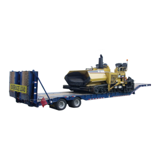
Slack Adjuster ..............29 List Of Figures Crewson Brunner Automatic Slack Adjuster ....29 Figure 1. Etnyre RPS Paver Special ......... 4 Recommended Preventive Maintenance ......29 Figure 2. Unit Nameplate or Certification Label ....5 Every Three Months or 25,000 Miles ......29 Figure 3. -
Page 5: Safety Precautions
This manual covers the standard features and op- tions of the Etnyre Paver Special series trailers. If your trailer incorporates custom features, some of the infor- DANGER - Immediate hazards which mation contained in this manual may not apply. -
Page 6: Unit Nameplate Or Certification Label
The certification label lists the correct rim size, tire persons operating or servicing an Etnyre trailer. Any size and tire inflation pressures for the trailer. warning or caution decal which is lost, or difficult to read, must be replaced at once. -
Page 7: Figure 3. Unit Nameplate And Decals
Care and maintenance information for your Etnyre trailer is given in the Maintenance section. Maintenance schedules and recommended procedures must be fol- lowed to maximize service life. 4,5,6 PATENTS PENDING PATENTS PENDING Thie Trailer is warning for the onlheing beofier ahen forest tr... -
Page 8: General Identification
General Identification Board-Apitong, 1.50 x 7.25 6321035 Drive Screw, Torx Hd, 5/16 x 3 1/8 6100396 Kingpin Q400449 Ramp Installation, 3' x 12' Q499330 Landing Gear Installation Q499334 Power Pack Bent Lash Ring Q508406 Tire & Wheel Asm Q496942-02... -
Page 9: Figure 4. Standard Hardware
SAE Grade 5 Capscrews SAE Grade 8 Capscrews Nominal Thread Torque Torque Torque Torque Size Series (ft. lbs.) (Nm) (ft. lbs.) (Nm) LUBED LUBED LUBED LUBED 20 UNC 28 UNF 5/16 18 UNC 24 UNF 16 UNC 24 UNF 7/16 14 UNC 20 UNF 13 UNC... -
Page 10: Trailer To Tractor Connect Procedure
This section contains information required for the 7. Check the lights, turn signals and reflectors for operation of Etnyre RPS model trailers. operation. WARNING Read these instructions thoroughly and observe them when operating Etnyre trailers. -
Page 11: General Rear Loading And Unloading Procedures
WARNING WARNING Use care when loading and unloading. Move Block the trailer wheels the machine on or off the trailer slowly! Extension bracket will not support the full load 3. Disconnect the fifth wheel lock pin. weight. 4. Pull tractor away from the trailer. 3. -
Page 12: Ramp Operating Instructions
To Raise Ramps WARNING 1. On Power Pack units, start the Power Pack. On Do Not bleed air from the tires when they are truck operated units, hook up the hydraulic lines and hot. engage the pump. 2. Raise the ramp to fully extended vertical position. 6. -
Page 13: Maintenance
It is outlined in two schedules: the mileage schedule This section contains instructions for the care and and the periodic schedule. Perform maintenance on the maintenance of the Etnyre RPS trailer. This section is basis of whichever occurs first. divided into two subsections: a Maintenance Sched- The first column of Maintenance Table 2 should be ule and Maintenance Procedures. -
Page 14: Figure 8. Maintenance Checkpoints
SCHEDULE ITEM NO. ITEM 25,000 mi. 50,000 mi. QUAN TYPE or REMARKS or 6 mo or 1 year Brakes Multipurpose Grease per axle Note: Do Not over-grease Brake Spider (or Anchor Pins when applicable) Check for Overheating Inspect & Adjust Lights &... -
Page 15: Maintenance Procedures
Table 3 lists the recommended electrodes for the speeds for long periods of time, could develop struc- various steels used in Etnyre trailers. tural damage faster than a trailer carrying lighter loads at lower speeds. Rough use and poor maintenance will Wheel Bearings shorten the life of the trailer. -
Page 16: Undercarriage
Undercarriage Service Guide - Ridewell Suspensions The undercarriage must be visually examined for Basic Operation broken and missing parts. Check brackets, adjusting When properly maintained and operated within de- screws and walking beam ends. Replace faulty parts. sign limits, Ridewell's Monopivot 240 Suspension will Check the rim clamps or cap nuts for tightness daily. -
Page 17: Air Pressure & Brake Protection Valve
Air Pressure & Brake Protection Valve x x x This air-ride suspension is dependent on air pres- Inspect for installation of anti-turn sure from the trailer supply system. Air pressure must washer for proper be maintained above 65 P.S.I. before operation. A Brake welding as shown Protection Valve must be installed in the air system to at right. -
Page 18: Welding Guidelines
Welding Guidelines Weld Joint Preparation A) All grease, dirt, paint, slag or other contami- The following precautions and recommendations nants must be removed from the weld joint without must be read and understood by qualified personnel gouging the axle tube. prior to weld installation of Ridewell Air-Ride Trailer Suspensions to trailer axles. -
Page 19: Repair Welding
D) Multiple pass welding may be used on the beam/ can only be repaired if the crack or break does not axle connection using the following guidelines. Total extend into the axle tube. To repair the weld, grid or fillet weld size should be 1/2" (12.7mm). back gouge the weld/crack down to the base metal. -
Page 20: Alignment Of Axle
Actuating Lever Arm YOUR SUSPENSION WILL HAVE THIS LABEL ABOVE THE ECCENTRIC BOLT 90º NOTICE! 45º (Optimal) ECCENTRIC BOLT ARROW MUST BE AT 12 O'CLOCK POSITION PRIOR TO ALIGNMENT. AFTER Down 45º ALIGNMENT INSTALL ANTI-TURN WASHER OVER Height Adjustable HEAD OF BOLT AND TORQUE at Hose Clamp TO 1,000 FT. -
Page 21: Valve Replacement
Rotate horizontal lever arm UP until grommet is at CAUTION axle mounting bracket pin level. Air springs should re- inflate to ride height level. Do not exceed the cold inflation pressures. In 5. Re-connect grommet to pin, Check to see if air some cases the rim will have a lower inflation springs are of equal firmness. -
Page 22: Matching Dual Tires
Matching Dual Tires Mounting and Demounting Tires on Disc Wheels Matching of the duals by size will result in longer tire life. Improper matching will cause the larger diam- eter tire to carry an overload. This will cause typical WARNING overloaded tire difficulties. -
Page 23: Checking Tightness On Mounted Dual Disc Wheels
10. If the inside tire and disc wheel assembly was not 7. Tighten the outer nut. removed, inflate the tire to the proper pressure. 8. The end play must be .001 in. (.0254 mm) to .010 in. (.254 mm). 9. Lock the outer spindle nut in place by bending Checking Tightness on Mounted Dual Disc the tangs or edge of the lockwasher over one flat on the Wheels... -
Page 24: Air Reservoir
Air Reservoir Brake Air Supply System Description Drain condensation from the reservoir while the res- (see Figure 21) ervoir is pressurized. Cables for the drain valves are The trailer relies on the tractor for its air supply. A located on the roadside of the trailer frame. Listen for description of the system operation follows: leaks after releasing the drain valve cables. -
Page 25: Relay Emergency Valve
will cause a full release of reservoir pressure into the 5. Apply soap suds at the pipe plugs and fittings. brake chambers, resulting in full brake application. Correct all leaks as indicated. 6. With the engine stopped and the pressure at 90 - 100 PSI (6.2 - 6.9 Bar) make and hold a full service Relay Emergency Valve brake application. -
Page 26: Brake Chambers
Brake Chamber Disassembly Brake Chambers 1. Clean the exterior of the brake chamber. (see Figure 23) 2. Put a mark on the parts so they can be reassembled Air pressure on the pressure plate side of the brake in the same relative positions. chamber diaphragm pushes the diaphragm against the push rod assembly. -
Page 27: Cleaning And Inspection Of Parts
General semble it with the non-pressure plate by working the clamp ring over the pressure plate. Align all the marks Etnyre trailers are equipped with cam actuated made during disassembly. brakes. Braking force is supplied by air pressure in the brake chamber, which pushes a push rod against the 7. -
Page 28: Slack Adjuster
Every Six Months or 50,000 Miles CAUTION The Gunite automatic slack adjusters are fac- tory lubricated and extensively sealed to protect against Do Not allow the linings to wear thin enough so dirt, water, salt and other corrosive elements. Never- the lining bolts or rivets contact the drum. -
Page 29: Boot Replacement
Boot Replacement Chamber Type .... Maximum Stroke (See Figures 32, 33 and 34) 12 ......less than 1-3/8" 16 ......less than 1-3/4" 1. Remove the 1/4” and 1/2” clevis pins. 20 ......less than 1-3/4" 2. Rotate the hex extension counterclockwise to clear 24 ...... -
Page 30: Slack Adjuster
Every Six Months or 50,000 Miles The Crewson Brunner automatic slack adjust- Link ers are factory lubricated and extensively sealed to pro- tect against dirt, water, salt and other corrosive elements. Nevertheless, periodic lubrication is recommended. Groove Boot 1. Grease the automatic slack adjuster. Insert (a) The styles of grease plugs or reliefs may vary according to models. -
Page 31: Slack Adjuster Replacement
7. Once the template has been swung into place, in- stall the 1/4” clevis pin. If the 1/4” pin does not slide Full OFF Position freely into the clevis and template, remove the tem- plate from the clevis. Rotate the clevis clockwise or Full ON Position counterclockwise several turns and reinstall the tem- plate in the clevis. - Page 32 stroke, or difference between these two measurements must be less than as shown on the following charts. Chamber Type Maximum Stroke 12.......... less than 1-3/8” 16.......... less than 1-3/4” 20.......... less than 1-3/4” 24.......... less than 1-3/4” 30.......... less than 2” Long Stroke Chamber Maximum Stroke 16...........
-
Page 33: Trouble Analysis For Air Brakes
CAUTION Check the brake adjustment frequently during the first 500 miles after relining. Overloading or using only the trailer brakes to stop the complete tractor-trailer unit will cause the heat absorption capacity of the brake to be exceeded. Hotter brake linings and drums, longer stopping distances, and shorter brake lining life will result. - Page 34 Trouble Analysis for Brakes (continued) Trouble Probable Cause Corrective Action Uneven brakes. See "Single brake dragging or locked" in this section. Restriction in brake hoses. Locate and remove restriction. Leaking brake chamber diaphragm. Replace diaphragm. Linings worn out. Reline brakes. Grease on linings.
- Page 35 Trouble Analysis for Brakes (continued) Trouble Probable Cause Corrective Action Insufficient brakes. Brakes need adjustment. Adjust brakes. Brakes need lubrication. Lubricate brakes. Lining worn away. Reline brakes. Defective relay emergency valve. Repair or replace valve. Brakes overheated. Stop and allow to cool. Locate the cause of overheating.
-
Page 36: Electrical
Use only Etnyre approved parts to ensure proper Lighting System functioning. First, apply a film of oil to the gasket and Etnyre trailer light wiring is color coded per SAE hand turn the filter until the gasket contacts the filter specifications. The standard trailer lighting system op- head. -
Page 37: Checking & Adjusting Relief Pressure At Control Valve
Checking and Adjusting Relief Pressure Pressure Gage on the Control Valve NOTE: Repair all hydraulic system oil leaks. The hydraulic oil level must be at the correct level. The hy- draulic pressure source must be operating properly be- fore checking and/or adjusting the hydraulic control valve relief pressure. -
Page 38: Trouble Analysis For Hydraulic Systems
Excessive hydraulic system noise. Air cavitating the system due to: a. Low oil level. Fill system. b. Suction line leaks air (foam Replace defective parts. Seal and present in tank). tighten leaking fittings. c. Incorrect hydraulic filter. Replace with Etnyre approved filter. -
Page 39: Electrical Hydraulic Power System - Q473524
Electrical Hydraulic Power System Schematic Q473524 14,15,16,17 10,11 3,4,22,23 27,29,30 20,21 21,24 21,26,27 28,31,32 Grn Wire Addition 24,27,32 21,20 21,24 REF PART NO. QTY DESCRIPTION REF PART NO. QTY DESCRIPTION Q466329 Elect. Hyd Module Q015154 Washer-Lock,1/4” Pkg 25 Q016828 Screw-Hex Hd, 3/8-16 x 1 1/4 Q428163 Plug-BWP 3039 Q015156... -
Page 40: Electro-Hydraulic Module - Q466329
Electro-Hydraulic Module Q466329 Pressure Hose Return Hose REF PART NO. QTY DESCRIPTION REF PART NO. QTY DESCRIPTION Q453433 Electric/Hyd Module 6602168 Cap-Hydr,08FJ 0122027 Screw-Hex, 5/16-18 x 1 1/4,Gr 2 PD Q012859 Adapter-St,Hex,04MP-08FP 0446363 Washer-Flat,5/16,PD Q436379 Breather 0120376 Nut-Hex, 5/16UNC,PD Q016074 Adapter-St,08MP-12MP Q014387 Plug-Pipe,1/2”... -
Page 41: Decals, Warnings & Id
REF PART NO. QTY DESCRIPTION REF PART NO. QTY DESCRIPTION Q452415 Decal-WARNING Proper Trl Oper Q492761 Decal: Warning, Bi-Fold Ramp, Bar 3390149 Plate-Name, Straight, ETNYRE Q474392 Instruction Decal Control Valve Q452390 Decal-Trademark, Patents Q474272 Decal-Selector Valve Q445617 Serial Plate Decal... -
Page 42: Ramp Installation
Ramp Installation Q499334 13,12 14,12 11,12 Pins come with cylinder REF PART NO. QTY DESCRIPTION REF PART NO. QTY DESCRIPTION Q466299 Ramp, Bi-Fold 12’, First Stage Q304529 Snap Ring Q499329 Ramp, Bi-Fold 12’, Second Stage Q466345 Q483897 Plate Q304525 Snap Ring Q482965 Washer Q484364... -
Page 43: Auxiliary Air Group - Q473908 - Thru S/N Q28299
Auxiliary Air Group Air Ride W/Manual Lowering System - Q473908 Up To S/N Q28299 Air Spring Air Spring (Ref) (Ref) Lock Down Valve Air Spring Air Spring (Ref) (Ref) Pilot Valve Height Control To Air Springs Valve (Ref) Reservoir Air Supply (Ref) Exhaust tube comes with this application. -
Page 44: Auxiliary Air Group - Q519023 - S/N Q28300 & Up
Auxiliary Air Group Air Ride W/Manual Lowering System - Q519023 S/N Q28300 and Up Delivery Port "N.O." Port Pilot Port 6" Long, To Atmosphere "N.C." Port Pilot Valve Switch "Cyl." Port Note: Switch must be "OFF" for automatic operation. NOTE: Ref. # 5 includes Ref. #'s 11 and 12 REF PART NO. -
Page 45: Air Schematic-W/Abs - Q502978 - Thru S/N Q27598
Air Schematic - 2 Axle With 2S/2M ABS Q502978 Thru S/N Q27598 Brake Chamber Ref 3,34 Service 18,41 21,22,23,24,35,36 9,37 16,30 13,37 13,27 21,22,23 17,40 28,31,32 20,42 Emergency 21,22,23 7,21,22,23,36,38 REF PART NO. QTY DESCRIPTION REF PART NO. QTY DESCRIPTION 0120918 Screw-Hex, 0.38NC x 1.50, GR2, PD Q402717... -
Page 46: Air Schematic-W/Abs - Q513583 - S/N Q27599 & Up
Air Schematic - 2 Axle With 2S/2M ABS Q513583 S/N Q27599 and Up Brake Chamber Ref 3,11 Service 10,14 24,29 15,19,25,27 19,30,31,32,33 18,22,26 Emergency REF PART NO. QTY DESCRIPTION REF PART NO. QTY DESCRIPTION 6309169 Tube-Nylon,Air,1/2,Generic 6601253 Coupling-Hose,Emergency,w/Filter 6601254 Coupling-Hose,Service,w/Filter 6600942 Elbow-Arbk,90,06MP-08MT Q400278... -
Page 47: Electrical Group - Q502012
Electrical Group - Q502012 MAIN CABLE STRIPPING DETAIL 1-3/8" BLUE WIRE 1-3/16" GREEN WIRE YELLOW WIRE BLACK WIRE RED WIRE BROWN WIRE 1/4" STRIP (7 PLACES) 1-1/8" WHITE WIRE See Stripping Detail For 7 Conductor Main Cable 6,11,12 2,13 18,19 2,13 18,19 2,13... -
Page 48: Electrical Group, Led - Q519546
Electrical Group, LED - Q519546 17,23 17,23 1,2,3,4 17,23 17,23 25,26 25,26 22,23 21,27 22,23 22,23 24,20 21,27 REF PART NO. QTY DESCRIPTION REF PART NO. QTY DESCRIPTION Q402185 Socket Asm-7 Pole w/Boot 6703109 Harness-Marker,S-T-T,RH,LED Q018465 CPSCR-1/4 UNC x 1,Gr 5 6703110 Harness-Marker,S-T-T,LH,LED Q015154... -
Page 49: Electrical Schematic - Abs 2S/2M - Q502897
MODULE 9,11 ATTENTION! Ref. #s 1, 3, 4, 5 and 6 are NOT AVAILABLE through the E.D Etnyre Co. Therefore, any re- placement parts will need to be obtained through your nearest Truck-Lite Dealer or Midwest Truck Parts Ph: 1-800-934-2727. -
Page 50: Electrical Schematic - Abs - S/N Q27599 & Up
Electrical Schematic-ABS S/N Q27599 and Up 7,8,10 9,10 Blue White 9,10 7,8,10 REF PART NO. QTY DESCRIPTION REF PART NO. QTY DESCRIPTION 6702506 Harness-ABS Power TL52100 x 120” 6451097 Sensor Asm-441 032 808 0 6703016 Harness-1.0 Meter Power Cable 6451076 Cable-Sensor, 1.8M Long 6702507 Harness-ABS Lamp Jumper... -
Page 51: Axle
Axle REF PART NO. QTY DESCRIPTION REF PART NO. QTY DESCRIPTION Q400676 Q400677 Nut-Lock Q400678 Q401262 Cone-Brg Outer Q435613 Cone-Brg Inner Q476230 Oil Seal (Guardian) ******* Axle Asm - Specify Serial Number of Trailer Specify Unit Serial No., Part No., & Part Description... - Page 52 This Page Intentionally Left Blank Specify Unit Serial No., Part No., & Part Description...
-
Page 53: Air Chamber - Slack Adjuster
Air Chamber - Slack Adjuster REF PART NO. QTY DESCRIPTION REF PART NO. QTY DESCRIPTION Q467849 Air Chamber Asm-5.56 Pushrod Q493542 Air Chamber Asm-5.15 Pushrod Q492170 Bracket, Air Chamber Q015160 5/8” Lockwasher Pkg Q015030 Q486619 Slack Adjuster-Auto, Gunite Q493461 Spring Brake Chamber Specify Unit Serial No., Part No., &... -
Page 54: Brake Assembly - 12-1/4 X 7-1/2
Brake Assembly - 12-1/4 X 7-1/2 Q507035 - Fast Change Includes Ref.#s (2-11) NOTE: Ref.# 2 includes (3-4). 24 25 18 19 Includes Ref.#s (21-23) Includes Ref.#s (13-17) 1-5/8 O LENGTH LEFT HAND RIGHT HAND 16.375 Q499269-01 Q499269-02 17.625 Q499269-03 Q499269-04 19.125 Q499269-05... -
Page 55: Tire & Wheel Assembly
Tire & Wheel Assembly REF PART NO. QTY DESCRIPTION REF PART NO. QTY DESCRIPTION Q473175 Wheel-Assembly,Accuride 6451380 Wheel Assembly,Hays Q471414 Valve-Dill #VS-900-572-03 Tire-Radial, 215/75R-17.5 LR (H) Q471412-02 Specify Unit Serial No., Part No., & Part Description... -
Page 56: Hub & Drum Assemblies
Hub & Drum Assemblies Right And Left Hand REF PART NO. QTY DESCRIPTION REF PART NO. QTY DESCRIPTION Q464574 Hub-RH Q435614 Cup-Bearing Q401263 Cup-Bearing Q464575 Hub-LH Q464571 Stud-RH Q441808 Brake Drum 63631 Q464573 Stud-LH 3100363 Nut-RH, Dual Wheel, 3/4-16, 10708 3100364 Nut-RH, Dual Wheel, 3/4-16, 10709 3100418... -
Page 57: Hendrickson - Air Suspension
Hendrickson - Air Suspension Q474767 Thru S/N Q28299 STANDARD TRAVEL 5.25" RIDE HEIGHT 5.25 Ride Height REF PART NO. QTY DESCRIPTION REF PART NO. QTY DESCRIPTION C-2870-1 Frame Bracket Assembly, 5.25” C2870-2 Frame Bracket Assembly, 5.25” Q483438 Shock Absorber A-1981 Air Spring Bolt Kit A-2116 Pvt Kit, Quick-Align... -
Page 58: Ridewell - Air Suspension
Ridewell - Air Suspension 6451350 S/N Q28300 and Up 6.50 Ride Height 2,3,4,5 13,14 REF PART NO. QTY DESCRIPTION REF PART NO. QTY DESCRIPTION LH Hanger Assembly Q513954 Lock Nut 3/4-10NC Oval 3267744C106 RH Hanger Assembly Q499116 Shock-Monroe 6 Stroke 3267744C206 Q513951 Eccentric Bolt-9 1/2 Lg. - Page 59 INDEX Part No. Page No. Part No. Page No. Part No. Page No. Part No. Page No. Part No. Page No. 0003650 6450575 6701385 Q016022 Q446363 0010700 6450954 6702028 Q016074 Q446478 6450956 6702090 Q016828 Q450083 0015011 0030700 6450956 6702116 Q017742 Q452390 0040700 6450962...
- Page 60 INDEX Part No. Page No. Part No. Page No. Part No. Page No. Part No. Page No. Part No. Page No. Q492170 Q492761 Q492761 Q492774 Q492775 Q492826 Q492826 Q493450 Q493451 Q493461 Q493542 Q495034 Q495036 Q495037 Q495040 Q495725 Q495726 Q495727 Q495727 Q495728 Q496961 Q499116...
- Page 61 If you find inaccurate or confusing information in this manual, or just have a suggestion for improvement, please let us know. Mail or FAX this form to us at: E. D. ETNYRE & CO. 1333 S. Daysville Rd. Oregon, Illinois 61061 • Fax: 800-521-1107 • www.etnyre.com...
Need help?
Do you have a question about the PAVER SPECIAL RPS Series and is the answer not in the manual?
Questions and answers