Sign In
Upload
Manuals
Brands
Etnyre Manuals
Utility Vehicle
PAVER SPECIAL RPS Series
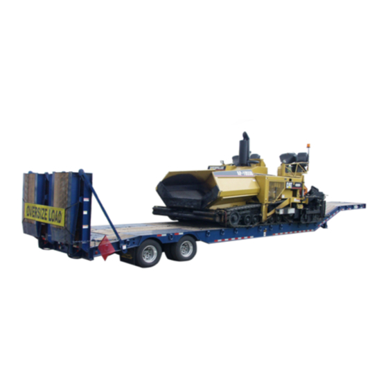
Etnyre PAVER SPECIAL RPS Series Manuals
Manuals and User Guides for Etnyre PAVER SPECIAL RPS Series. We have
1
Etnyre PAVER SPECIAL RPS Series manual available for free PDF download: Parts And Operation Manual
Etnyre PAVER SPECIAL RPS Series Parts And Operation Manual (61 pages)
Brand:
Etnyre
| Category:
Utility Vehicle
| Size: 0 MB
Table of Contents
Warranty
2
Table of Contents
3
List of Figures
4
Safety Precautions
5
Hazard Seriousness Level
5
Reporting Safety Defects
5
Figure 1. Etnyre RPS Paver Special
5
Unit Nameplate or Certification Label
6
Serial Number Data
6
Trailer Capacity Data
6
Tire and Rim Data
6
System Specifications
6
Operating Instructions
6
Warning and Caution Information
6
Figure 2. Unit Nameplate or Certification Label
6
Figure 3. Unit Nameplate and Decals
7
General Identification
8
Figure 4. Standard Hardware
9
Trailer to Tractor Connect Procedure
10
Trailer to Tractor Disconnect Procedure
10
Figure 5. Inspection of Kingpin for Wear
10
General Rear Loading and Unloading Procedures
11
General Road Check Procedures
11
Ramp Operating Instructions
12
Figure 6. Bi-Fold Ramps
12
Figure 7. Control Valve Positions
12
Maintenance
13
Maintenance Schedule
13
Figure 8. Maintenance Checkpoints
14
Maintenance Procedures
15
Frame Inspection
15
Weld Repairs
15
Wheel Bearings
15
Undercarriage
16
Service Guide - Ridewell Suspensions
16
Basic Operation
16
Air Springs & Height Control Valve
16
Figure 9. Check Oil Level of Oil Lubricated Bearings
16
Figure 10. Tightening Sequence
16
Air Pressure & Brake Protection Valve
17
Operational Inspection
17
Preventive Maintenance
17
Daily
17
Every 30 Days
17
Every 90 Days & with Annual Inspection
17
Figure 11. Eccentric Bolt Inspection
17
Welding Guidelines
18
Welding Methods, Materials & Personnel
18
Weld Joint Preparation
18
Welding Procedure
18
Figure 12. Root Weld Gap
18
Figure 13. Multiple Pass Recommended Method
18
Repair Welding
19
Welding Precautions
19
Figure 14. no Weld Zones
19
Figure 15. Alignment of Axle
19
Alignment of Axle
20
Height Control Valve Operation
20
Set up
20
Adjustment
20
Figure 16. Hanger Sticker
20
Figure 17. Height Control Valve Asm
20
Valve Replacement
21
Tires and Disc Wheels
21
Tire Inflation
21
Tire Overinflation
21
Tire Underinflation
21
Figure 18. Proper Tire Inflation
21
Matching Dual Tires
22
Removing Tire and Disc Wheel Assembly
22
Mounting and Demounting Tires on Disc Wheels
22
Mounting Tire and Hub Piloted Type Disc Wheels
22
Figure 19. Removal of Tires & Hub Piloted Wheels
22
Checking Tightness on Mounted Dual Disc Wheels
23
Hubs
23
Figure 20. Checking Oil Level in Hub
23
Hub Removal
23
Inspection and Cleaning
23
Hub Installation
23
Air Systems and Brakes
23
Air Systems and Brakes - General
23
Air System Tests
23
Figure 21. Brake Air Supply System - 2 Axle Shown
24
Air Reservoir
24
Air Hoses and Tubing
24
Brake Relay Emergency Valve
24
Air Brake Chambers
24
Brake Air Supply System Description
24
Figure 22. Relay Emergency Valve
25
Relay Emergency Valve
25
Figure 23. Brake Chamber
26
Brake Chambers
26
Brake Chamber Servicing
26
Brake Chamber Removal
26
Brake Chamber Disassembly
26
Cleaning and Inspection of Parts
27
Brake Chamber Assembly
27
Installation
27
Trailer ABS
27
Air Brakes
27
General
27
Operating Checks
27
Brake Assembly
27
Figure 24. Brake Components
28
Figure 25. Lubrication Point- Slack Adjuster
28
Slack Adjuster
28
Gunite Automatic Slack Adjuster
28
Recommended Preventative Maintenance
28
Every Three Months or 25,000 Miles
28
Every Six Months or 50,000 Miles
28
Testing Adjuster Function
28
Figure 26. Adjuster Function
29
Figure 27. Clevis Pins, Hex Extension and Boot
29
Figure 28. Boot
29
Boot Replacement
29
Boot
29
Slack Adjuster
30
Crewson Brunner Automatic Slack Adjuster
30
Recommended Preventive Maintenance
30
Every Three Months or 25,000 Miles
30
Every Six Months or 50,000 Miles
30
Testing Adjuster Function
30
Figure 29. Boot Position
30
Figure 30. Slack Adjuster Lubrication Points
30
Slack Adjuster Replacement
31
Figure 31. Measuring Maximum Stroke
31
Trouble Analysis for Air Brakes
33
Electrical
36
Lighting System
36
Hydraulics
36
General
36
Hydraulic Power Pack Filter
36
Checking Hydraulic Rex/Rvoir Oil Level
36
Changing Hydraulic Oil
36
Figure 32. Gooseneck Socket Connection
36
Figure 33. Hydraulic Oil Check
36
Checking & Adjusting Relief Pressure at Control Valve
37
Figure 34. Directional Control Valve Pressure Relief
37
Trouble Analysis for Hydraulic Systems
38
Electrical Hydraulic Power System - Q473524
39
Electro-Hydraulic Module - Q466329
40
Decals, Warnings & ID
41
Ramp Installation
42
Auxiliary Air Group - Q473908 - Thru S/N Q28299
43
Auxiliary Air Group - Q519023 - S/N Q28300 & up
44
Air Schematic-W/Abs - Q502978 - Thru S/N Q27598
45
Air Schematic-W/Abs - Q513583 - S/N Q27599 & up
46
Electrical Group - Q502012
47
Electrical Group, LED - Q519546
48
Electrical Schematic - ABS 2S/2M - Q502897
49
Electrical Schematic - ABS - S/N Q27599 & up
50
Axle
51
Air Chamber - Slack Adjuster
53
Brake Assembly - 12-1/4 X 7-1/2
54
Tire & Wheel Assembly
55
Hub & Drum Assemblies
56
Hendrickson - Air Suspension
57
Ridewell - Air Suspension
58
Advertisement
Advertisement
Related Products
Etnyre PRTN55ETD3-T1
Etnyre PRTN55TD3-T1
Etnyre PavementSaver III
Etnyre Black-Topper BT-1 Distributors 2008
Etnyre Black-Topper BT-1 Distributors 2009
Etnyre Black-Topper BT-1 Distributors 2010
Etnyre Black-Topper BT-1 Distributors 2011
Etnyre Black-Topper BT-1 Distributors 2012
Etnyre Black-Topper BT-1 Distributors 2013
Etnyre Black-Topper BT-1 Distributors 2014
Etnyre Categories
Utility Vehicle
Construction Equipment
Amplifier
Industrial Equipment
More Etnyre Manuals
Login
Sign In
OR
Sign in with Facebook
Sign in with Google
Upload manual
Upload from disk
Upload from URL