
Related Manuals for Etnyre Black-Topper SHOOTER Series


Summary of Contents for Etnyre Black-Topper SHOOTER Series
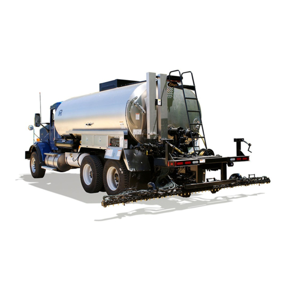
- Page 1 M-421-03 Starting with Serial Number M-4500 Supersedes Manual M-421-99 Updated June 29, 2021 Black-Topper ® SHOOTER Series with Computer Controls Asphalt Distributor...
-
Page 2: How To Order Parts
Specify unit serial number when ordering parts! WARRANTY E. D. Etnyre & Co. warrants to the original Purchaser, its new product to be free from defects in material and workmanship for a period of twelve (12) months after date of delivery to original Purchaser. -
Page 3: Safety Precautions
You will find safety information boxes throughout this manual. These boxes contain information alerting If you have any questions about operation of this machine, contact the Etnyre Service you to situations or actions to avoid. Department at 1-800-995-2116 or Signal Words (DANGER, WARNING and 1-815-732-2116. -
Page 4: Table Of Contents
Hazard Seriousness Level..........2 LPG Burners ............... 46 LPG Burners with Outfire..........47 GENERAL Thermocontrol - 12 Volt Etnyre LPG Burners ..... 48 Reporting Safety Defects..........4 Thermocontrol - 12 Volt Etnyre LPG Burners ..... 49 LPG Tank ..............50 DECALS &... -
Page 5: Reporting Safety Defects
E. D. Etnyre Service Administration (NHTSA) in addition to notifying E.D. Department at 1-800-995-2116. -
Page 6: Warning And Instruction Plates
Plate-Warning. Asphalt Grades 3390679 Plate-Warning, Manhole 3390655 Plate-Name, Distributor, Brass 3390684 Plate-Caution, Hot Surface 3390591 Tag-Caution, Handspray Hose 3390191 Decal-Oval, Etnyre 3390659 Decal-Warning, GVWR 3390540 Plate-Directions, LPG Burner 3390669 Decal-Handspray Operation 3390670 Plate-Directions, Ele. Fuel Oil Burner 3390531 Plate-Warning, Sample Valve... -
Page 7: Control Panel And Stand
Control Panel And Stand NOTE: Computer is installed in a remote location such as behind the truck seat. 6, 13 6, 7 6, 7 SPRAYBAR POWER 21, 22 APPLICATION CIRCULATION RATE MEMORY RATE CHANGE RESET RESET FEET DISPLAY GALLONS METRES LITRES HYD OIL WING FOLD... -
Page 8: Control Panel Assembly - Rear
Control Panel Assembly - Rear 2,3,4,5 IF T L IF PUMP GPM CONTROL MASTER POWER W IN FRONT REAR IN G BURNER CONTROL UPPER LOWER 26 60 16 6 WASHDOWN / FLUSHING WING FOLD SHIFT LIFT 2660166 REF PART NO. QTY DESCRIPTION REF PART NO. -
Page 9: Radar Speed Sensor Installation
Radar Speed Sensor Installation 3, 4, 5, 6 3, 4, 5, 6 35º 7, 8, 9, 10 7, 8, 9, 10 Torque to 30 - 35 lb/in FORWARD NOTE: If the display shows feet traveled less than an actual 18" to 36" measured course decrease the mounting angle, change from 35º... - Page 10 Section Notes Specify Unit Serial No., Part No., & Part Description...
-
Page 11: Strainer Box Assembly - Thru S/N M4800
Strainer Box Assembly - Thru S/N M4800 16 28 35 36 12 37 39 40 16 12 50,51 Specify Unit Serial No., Part No., & Part Description... - Page 12 Strainer Box Assembly - Thru S/N M4800 REF PART NO. QTY DESCRIPTION REF PART NO. QTY DESCRIPTION 2640746 Housing Weldment-Strainer 2640923 Gasket-Fill Line 2640750 Strainer Asm-Asphalt Pump, 7" Dia 3350917 Bolt-Carriage,1/2 x 5 2640736 Lid-Strainer Box, Weldment 3350919 3341078 Ring Asm-Clamping, Transfer Valve 3350918 Bushing Note: part of ref.
-
Page 13: Strainer Box Assembly - S/N M4801 & Up
Strainer Box Assembly - S/N M4801 & Up 16 28 35 36 7 36 32 30 39 40 50,51 Specify Unit Serial No., Part No., & Part Description... - Page 14 Strainer Box Assembly - S/N M4801 & Up REF PART NO. QTY DESCRIPTION REF PART NO. QTY DESCRIPTION 2640746 Housing Weldment-Strainer 2640852 Cyl Body-Suction, Dbl Piston 2640750 Strainer Asm-Asphalt Pump, 7" Dia 2640923 Gasket-Fill Line 2640736 Lid-Strainer Box, Weldment 2640843 Gasket-Strainer Box Lid 3341078 Ring Asm-Clamping, Transfer Valve...
-
Page 15: Way Valve With Relief
4 Way Valve with Relief 2640827 Return To Tank 55,56 Specify Unit Serial No., Part No., & Part Description... - Page 16 4 Way Valve with Relief 2640827 REF PART NO. QTY DESCRIPTION REF PART NO. QTY DESCRIPTION 2640771 Valve Stem-Relief 6100425 Spring-Medium Pressure Die 0426898 Nut-Hex, Jam, 0.88NC, EA, PD 6601177 Valve-Ball, 1 In, Hand Spray 6001119 Washer-Flat, 0.88, PN 6602151 Scraper-Nitrile, 1.00 ID x 1.5 OD 2640806 Cover Asm-Relief Spring...
-
Page 17: Way Valve With Relief, Air Operated
4 Way Valve with Relief, Air Operated 2640835 Return To Tank Specify Unit Serial No., Part No., & Part Description... - Page 18 4 Way Valve with Relief, Air Operated 2640835 REF PART NO. QTY DESCRIPTION REF PART NO. QTY DESCRIPTION 2640771 Valve Stem-Relief 6602151 Scraper-Nitrile, 1.00 ID x 1.5 OD 0426898 Nut-Hex, Jam, 0.88NC, EA, PD 6602152 O-Ring-1.25 OD x 0.125 6001119 Washer-Flat, 0.88, PN 2640831 Cylinder Weldment-Full Cab Ctrls...
-
Page 19: Pump Assembly - 200Mu
Pump Assembly - 200MU 2640609 Dots this side (4) Dots this side (3) REF PART NO. QTY DESCRIPTION REF PART NO. QTY DESCRIPTION 2640607 Portside End Plate-Machined 2640932 Gasket-Pump 6420211 Bushing-1.44 ID x 1.75 x 1.25 Lg 3361274 Asphalt Pump Shaft Guard 3340279 Impeller-Herringbone, LH w/Key 6602658... -
Page 20: Pump Assembly - 400Mu
Pump Assembly - 400MU 2640698 Dots this side (4) Dots this side (2) Dots this side (3) Dot this side (1) REF PART NO. QTY DESCRIPTION REF PART NO. QTY DESCRIPTION 0211887 Screw-Hex, 1/4NC x 3/4, Gr 2, PD 2640607 Portside End Plate-Machined 2640885 Nut-Packing, P15 Pump... -
Page 21: Hydraulic
Hydrostatic Drive System - PTO Driven 42 Series Pump RH - Right Hand Pump Shown OPTIONAL For LH Main Pump Ref. 33: High Presure Line is connected to "A" Low Pressure Line is connected to "B". Return From See "Drivelines - PTO to Pump Hydraulic Pump". - Page 22 Hydrostatic Drive System - PTO Driven 42 Series Pump REF PART NO. QTY DESCRIPTION REF PART NO. QTY DESCRIPTION 6601135 Elbow-Hyd, 90, 16MP-16MJ 9250611 Hose Asm-LP, 12-16FJX-16FJX 6601566 Hose End, 16-16FJX, ST (Specify Length) 6000792 Clamp-Hose, Worm Dr., 1.06 to 2 9250610 Hose Asm-HP 12-16FJX-16FJX 6601564...
-
Page 23: Station Manifold Assembly
4 Station Manifold Assembly Rt Wing Rod End Rt Wing Blind End Lt Wing Rod End Lt Wing Blind End Shift Rod End Shift Blind End Rt Lift Blind End Lt Lift Blind End Rt Lift Rod End Lt Lift Rod End REF PART NO. -
Page 24: Schematic - 6602356 Hydraulic Manifold Block
Schematic - 6602356 Hydraulic Manifold Block Call w/ Serial Number Lower when ordering Feed Right Wing Tube Assembly Item Raise 12 & 13 Lower Left Wing Raise Shift Left Shift Right ORF 2 ORF 3 1500 ORF 4 AUX P AUX T Specify Unit Serial No., Part No., &... -
Page 25: Hydrostatic Drive System - Crankshaft Driven
Hydrostatic Drive System - Crankshaft Driven 42 Series Pump To obtain tube length "A", measure OPTIONAL Custom Adapter pump shaft to crank end of truck engine (where required) (or adapter if required) and subtract 6" Specify Distributor serial Crank end of Hydraulic number. -
Page 26: Drive Line - Pto To Hydraulic Pump - 42 Series
Drive Line - PTO to Hydraulic Pump 42 Series Pumps TUBE LENGTH "A" AND "C" Locate Center Bearing (Ref 7) at desired location. For tube length "A", measure "B" dimension from face of Hydraulic Pump Shaft to center of Bearing (Ref 7) and subtract 6-7/8"... -
Page 27: Drive Line - Pto To Hydraulic Pump - Gmc Trucks
Drive Line - PTO To Hydraulic Pump - GMC Trucks 42 Series and 90 Series Hydraulic Pumps Truck End Apply Anti-Seize compound to shaft before sliding in yoke 13.75 Max 0.94 11.88 Max Hydraulic Pump 16.03 Max REF PART NO. QTY DESCRIPTION REF PART NO. -
Page 28: Spray Bar Nozzle Chart
Spray Bar Nozzle Chart Application Application US Flow Specify Unit Serial No., Part No., & Part Description... -
Page 29: Spray Bar Assembly - 12 Ft. - Gang On/Off
Spray Bar Assembly - 12 Ft. - Gang On/Off 8 Ft. Center Section Specify Unit Serial No., Part No., & Part Description... - Page 30 Spray Bar - 12 Ft - Gang On/Off 8 Ft. Center Section REF PART NO. QTY DESCRIPTION REF PART NO. QTY DESCRIPTION 2650523 Center Bar Weldment, 8 Ft Nozzle----------See Spray Bar Nozzle 2650503 Spray Bar-Wing Weldment, RH Chart (p27) for Part No. 2650501 Spray Bar-Wing Weldment, LH 7230428...
-
Page 31: Spray Bar - 8 Ft. - 1 Foot Controls
Spray Bar - 8 Ft. - 1 Foot Controls Specify Unit Serial No., Part No., & Part Description... - Page 32 Spray Bar - 8 Ft - 1 Foot Controls REF PART NO. QTY DESCRIPTION REF PART NO. QTY DESCRIPTION Nozzle----------See Spray Bar Nozzle 2650541 Center Bar Weldment, 8 Ft, 1’Control Chart (p27) for Part No. 2650538 Spray Bar-Wing, 1' Cont, RH 3352524 Plug 2650537...
-
Page 33: Hydraulic Raise & Shift - Thru S/N M4635
Hydraulic Raise & Shift - Thru S/N M4635 10 9 9,10 10 9 REF PART NO. QTY DESCRIPTION REF PART NO. QTY DESCRIPTION 2650560 Drop Tube & Hanger Plate Asm 2650513 Plate-Arm, Bar Carry 2 6602709 1 Cylinder-Air, 2.0 X 10.0, Modified 0120233 Screw-Hex,0.38NC x 1.00, Gr2, PD 2650519 Lug Asm-Bar Shift 0120382... -
Page 34: Hyd Raise & Shift - S/N M4636 & Up
Hyd Raise & Shift - S/N M4636 & Up REF PART NO. QTY DESCRIPTION REF PART NO. QTY DESCRIPTION 2650615 Drop Tube & Hanger Plate Asm 0121574 Washer-Lock, 0.62, Spring, PD 6601775 Cylinder-Hyd, 2.0 x 12.0 0124589 Nut-Hex, 0.62NC, PD 2650617 Side Shift Vertical Pivot-Bar Carry 6601781... -
Page 35: Coaxial Hose - Spray Bar Feed
Coaxial Hose - Spray Bar Feed Asphalt Pump Swivel arrangement for units with Spraybar Side Shift Spraybar REF PART NO. QTY DESCRIPTION REF PART NO. QTY DESCRIPTION 0124589 Nut-Hex, 0.62NC, PD 2650584 Transition-Swivel, Siamese Hose 3352615 Gasket-Spraybar Swivel 2640461 Gasket-Adpt Flange LL32 Pump 7230219 Swivel Asm-Hinge Sec Mod Bar 2650598... -
Page 36: Bar Latch - Manual
Bar Latch - Manual REF PART NO. QTY DESCRIPTION REF PART NO. QTY DESCRIPTION 6000802 Spring 3380718 Latch Asm-LH 4420933 Handgrip (Optional) 3380719 Latch Asm-RH 3380716 Latch Cam Asm-LH 3380869 Spacer-Bracket, Latch Asm 3380717 Latch Cam Asm-RH 9411727 Lock Nut, 0.50NC 9411417 Flat Washer, 0.50 3380714... -
Page 37: Spray Bar Wing Raise - Manual
Spray Bar Wing Raise - Manual REF PART NO. QTY DESCRIPTION REF PART NO. QTY DESCRIPTION 3361128 Wing Up, Short Bar 2650506 Lug Asm-Wing Retract 6420194 Bushing-DU, 1x1.12x1 (Included with Ref 2) 0180181 Screw-Hex, 0.50NCx2.00, GR5, PD 0120384 Washer-Lock, 0.50, Spring, PD 0114951 Washer-Flat, 0.50, PN 3361127... -
Page 38: Spray Bar Wing Raise - Hydraulic
Spray Bar Wing Raise - Hydraulic REF PART NO. QTY DESCRIPTION REF PART NO. QTY DESCRIPTION 6602230 Cylinder-Hyd, 2.0 x 10, Wing Up 2650506 Lug Asm-Wing Retract 6420194 Bushing-DU, 1x1.12x1 (Included with Ref 2) 0180181 Screw-Hex, 0.50NCx2.00, GR5, PD 0120384 Washer-Lock, 0.50, Spring, PD 0114951 Washer-Flat, 0.50, PN... -
Page 39: Handspray
Handspray From Handspray CAUTION: Replace Rubber Handspray Control Valve Hose Only With Original Equipment Hose From E. D. ETNYRE & Co Optional Hose Reel From Handspray Control Valve Handspray REF PART NO. QTY DESCRIPTION REF PART NO. QTY DESCRIPTION 3380785... -
Page 40: Power Washdown And Self Flushing System
Power Washdown and Self Flushing System NOTE: Tee and Hose Barbs are used for Beckett Burners REF PART NO. QTY DESCRIPTION REF PART NO. QTY DESCRIPTION 3331415 Tank Asm-Fuel, 12 x 50 0119920 Nipple, 0.25 x 2.00 6100235 Filler Cap 6600303 Valve-Globe, 0.25, ST 3360180... -
Page 41: Fuel Tank Kassembly And Self Flushing Line
Fuel Tank Assembly and Self Flushing Line NOTE: Tee and Hose Barbs are used for Beckett Burners REF PART NO. QTY DESCRIPTION REF PART NO. QTY DESCRIPTION 1 3331415 Tank Asm-Fuel, 12 x 50 16 6600303 Globe Valve, 0.25 In., ST 2 6100235 Filler Cap 17 6602402... -
Page 42: Air Supply - Gang On/Off
Air Supply - Gang On/Off 4, 5 & 36 Frame To Air Cylinders REF PART NO. QTY DESCRIPTION REF PART NO. QTY DESCRIPTION 6450357 Air Reservoir, 0.69 x 22.5 0120128 Nipple, Sch 40, 0.38 x 3.5 3361119 Bracket - Long 6701510 Romex Connector, 0.75 3361163... -
Page 43: Air Supply - 1 Foot Controls
Air Supply - 1 Foot Controls Frame Specify Unit Serial No., Part No., & Part Description... - Page 44 Air Supply - 1 Foot Controls REF PART NO. QTY DESCRIPTION REF PART NO. QTY DESCRIPTION 6600324 AR Hose, 0.38, Per/Ft. 6600306 Hose End, 06FSX, St, LPSP 6200179 Elbow, 0.38 Tube x 0.38NPT, 90 Deg. 0109421 Nipple, 0.38 x 1.50 Cl,PN 0120280 Tee-Pipe, 0.38NPT, PD 0119931...
-
Page 45: Fuel Oil Burner Installation
Fuel Oil Burner Installation 9 - 19 (Assembled) Return To Fuel Tank From Fuel Tank Burner Relay and Fuse Installation is shown on next page. A Wiring Diagram for Burner To Strainer Box Controls appears in the Wiring Diagrams section in the back of this manual. -
Page 46: Relay And Fuse - Fuel Oil Burner
Relay and Fuse - Fuel Oil Burner 7230287 TO REAR CONTROL BOX 5, 15 10 GA. RED X 22' (2) 12, 14 1/4" LOOM X 21' (1) MOTOR 14GA. ORANGE X 22' BURNERS 10 GA. RED X 20' (2) 1/4" LOOM X 19' (1) 6, 7 5, 15 LOWER... -
Page 47: Lpg Burners
LPG Burners NOTE: Ref. 1, Burner Assembly includes Ref. 2, 3 & 4 ONLY. 10 11 1 0 0 From Fuel Supply 28, 29 REF PART NO. QTY DESCRIPTION REF PART NO. QTY DESCRIPTION 3331073 Burner Asm 6200417 Nipple-Sch 80, 0.25 x 1.50 3331036 Vapor Plug Holder 3331362... -
Page 48: Lpg Burners With Outfire
Ref. 2, 3 & 4 Only. 13 14 FROM CONTROL BOX REF PART NO. QTY DESCRIPTION REF PART NO. QTY DESCRIPTION 3331073 Burner Asm-LPG Etnyre 6500020 Shut Off-12 V, B-3 Burner 3331036 Holder-Vapor Plug 24 3331879 2 Angle-Mt Outfire Box 3331086 Nozzle-L.P.G. Burner Etnyre 6200419 Nipple-PP, Sch 80, 0.25 x 3.50, PD... -
Page 49: Thermocontrol - 12 Volt Etnyre Lpg Burners
Thermocontrol - 12 Volt Etnyre LPG Burners Set up both burners as shown below Detail of Thermocontrol Box 1/16" to 1/8" Spark Gap To Pilot Light Ignitor Pilot 32,33,50 32,33,34 Well - Thermometer Installation 35,36,37,38 32,33,39 Rear Jacket Rear Tank Head From LPG Supply Specify Unit Serial No., Part No., &... -
Page 50: Thermocontrol - 12 Volt Etnyre Lpg Burners
Thermocontrol - 12 Volt Etnyre LPG Burners REF PART NO. QTY DESCRIPTION REF PART NO. QTY DESCRIPTION 6500192 Control-Flame Out & Temp, LPG 6309071 Tube-0.38 x 0.25 Copper, Type L 3331073 Burner Asm-LPG 0121867 Screw-Hex, 0.25NC x 0.75,GR2,PO 3331877 Pilot Asm W/Plug & Mtg. Brkt. -
Page 51: Lpg Tank
LPG Tank To Burners 17,19,20 REF PART NO. QTY DESCRIPTION REF PART NO. QTY DESCRIPTION 6500333 Tank-LPG, 42 Gal., 18 x 42, Chassis 7720063 Gauge-Sight, Tank LPG 18 x 42 + 53 6500045 Tank-LPG, 52 Gal., 18 x 53, Chassis 9422850 Washer-Flat, 0.62A (0.65 x 1.31)HN 6500360... -
Page 52: Lpg Portable Burner - Tank System
LPG Portable Burner - Tank System NOTE: Ref. 2 Includes Ref. 3. Without Thermocontrol To Burners With Thermocontrol From Fuel Supply From Fuel Supply Thermocontrol To Portable Burner To Portable Burner REF PART NO. QTY DESCRIPTION REF PART NO. QTY DESCRIPTION 3331899 Burner Asm W/O Hose... -
Page 53: Exhaust Stacks
Exhaust Stacks REF PART NO. QTY DESCRIPTION REF PART NO. QTY DESCRIPTION 2630421 Stack Asm-39 1/2" Lg (36 x 70) 2630426 Stack-Flue,34 3/4" Lg (36 x 70) 2630419 Stack Asm-57" Lg (53 x 88) 2630424 Stack-Flue,521/4" Lg (53 x 88) 2630423 Stack Asm-48 3/4"... -
Page 54: Manhole & Strainers
Manhole & Strainers REF PART NO. QTY DESCRIPTION REF PART NO. QTY DESCRIPTION 2600379 Cover Asm-20, Manhole 3390679 Plate-Warning, Manhole 2700248 Gasket-Cover, MH, Non Rel, 20 3390684 Plate-Caution, Hot Surface 6001133 Garlock-Packmasters, 3/4" Sq 2690170 20” Strainer 0444867 Plug-Auto, Hex Sock, 0.38NPTF, PD 3390695 6”... -
Page 55: Tank Gauge Assembly
Tank Gauge Assembly (Ref. 1 includes items 2, 3, 4, 5, 6, 7 and 9) NOTE: When ordering Tank Gauge Dial (Ref. 13) please include: 1. Unit Serial Number 2. Tank Oval Size 3. Tank Capacity 4. Specify Front or Rear Dial Tank Shell Install with drain hole... -
Page 56: Ladder
Ladder 14 15 REF PART NO. QTY DESCRIPTION REF PART NO. QTY DESCRIPTION 0454908 Screw-Hex, 3/8NC x 2, GR8, PD 0121574 2 Washer-Lock, 5/8, Spring, PD 0180175 Screw-Hex, 1/2NC x 1 1/4, GR2, PD 0124589 2 Nut-Hex, Lock, 5/8NC, Ea, PD 2680450 Scissor Asm-Upper Ladder 0130999... -
Page 57: Sample Valve - Thermometers - Temperature Probe
Sample Valve - Thermometers - Temperature Probe Rear Tank Rear Sample Valve Shell Tank Head Inside of Tank Belly of Tank To Computer Electric Temperature Probe REF PART NO. QTY DESCRIPTION REF PART NO. QTY DESCRIPTION 3300773 Ring-Finishing 0140798 Elbow-PP, 45, ST, 0.75NPT 0144034 Bushing-Pipe, 0.75 x 0.50NPT, PN 6600349... -
Page 58: Fender Assemblies
Fender Assemblies Tandem Fender Single Axle Fender REF PART NO. QTY DESCRIPTION REF PART NO. QTY DESCRIPTION 3380835 Fender-Single Axle, Alum 3380837 Strap-Mtg, Fender, Front 3311427 Mounting Bracket 3380839 Bracket-Mtg, Tandem 0122017 AR Screw-Hex, 5/16NC x 1 0120377 Nut-Hex, 3/8NC 0446363 AR Washer-Flat, 5/16 0120382... -
Page 59: Tool Boxes
Tool Boxes REF PART NO. QTY DESCRIPTION REF PART NO. QTY DESCRIPTION 2680469 51” Toolbox Asm, LH 3311629 51” Toolbox Asm, RH 3311624 Door - 51” Toolbox 6000255 AR Lock 3311625 Hinge-Piano - 51” Toolbox AR = As Required Specify Unit Serial No., Part No., & Part Description... -
Page 60: Bar Box Assemblies
Bar Box Assemblies REF PART NO. QTY DESCRIPTION REF PART NO. QTY DESCRIPTION 3352684 Bar Box Asm 3352678 3352683 Pin-Hinge 6001161 Latch-T Handle 0219301 Plug-Pipe, SqHd, 3/4 NPT 3352424 Box Asm-Section Carrier 6000308 Safety Hasp 0219303 Plug-Pipe, SqHd, 1 NPT Specify Unit Serial No., Part No., &... -
Page 61: Miscellaneous Attachments And Tools
Miscellaneous Attachments and Tools REF PART NO. QTY DESCRIPTION REF PART NO. QTY DESCRIPTION 7230372 Switch-4 Way (located in cab) 6600250 Dust Cap, 3”, Brass Measuring Stick (1 Flue) 6600279 Gasket-3” ID, Silicone ******* Call with Unit Serial Number 6600278 3”... -
Page 62: Tank Mounting
Tank Mounting Left Side Of Vehicle Shown NOTE: Units that are over 2,500 Gals., add (1) spring loaded tie down F r o bolts to the (2) front most 6 thru 10 & 13 mounting channels. NOTE: Ref. 1, Motion Limiter, One (1) on each side. -
Page 63: Pintle Hook
Pintle Hook REF PART NO. QTY DESCRIPTION REF PART NO. QTY DESCRIPTION 6001167 Pintle Hook 9414000 Lock Nut, 0.75NC, GR8 0131000 Flat Washer, 0.75 0223529 Screw, 0.75NC x 2.50, GR8 3300104 Lifting Bracket 3300106 Lifting Ring 6001115 Screw, 0.75NC x 2.25, GR8 Specify Unit Serial No., Part No., &... -
Page 64: Identification And Clearance Lights
Identification and Clearance Lights 9, 10 REF PART NO. QTY DESCRIPTION REF PART NO. QTY DESCRIPTION 1 6700084 1 Identification Lamp • • • • • • • AR Strobe Light (Specify Serial Number) 6700455 O Ring • • • • • • • AR Mounting Bracket(Specify Serial No.) 6700284 Red Lens... -
Page 65: Bumper Assemblies
Bumper Assemblies 24,26,27 Econo Bumper Assembly Existing Light From Truck Existing Light 4 Wire Bumper Assembly From Truck 24,26,27 5 Wire Bumper Assembly Specify Unit Serial No., Part No., & Part Description... - Page 66 Bumper Assemblies REF PART NO. QTY DESCRIPTION REF PART NO. QTY DESCRIPTION 3370757 Bumper Asm - 4 Wire Conduit 3312136 Frame Asm 6701076 Elbow-Auto, 90, 04MP-06T Poly 4 6000686 4 Reflector-Red 2780432 Bumper Asm 2770093 Light Box - RH 2770096 Light Box - LH 6700037 Clearance Light, 12V...
-
Page 67: Wiring Diagram - Lighting
Wiring Diagram - Lighting REAR SIDEMARKER - Red FRONT IDENTIFICATION RIGHT REAR CLEARANCE CLEARANCE Red Amber 4 WIRE TRUCK ENVIRONMENTAL STOP, TAIL and TURN Brown 14 BACK-UP Green 14 Yellow 14 Gray 14 STOP, TAIL and TURN FRONT LEFT REAR CLEARANCE CLEARANCE Red Amber... -
Page 68: Wiring Diagram - Radar And Pump Tachometer
Wiring Diagram - Radar and Pump Tachometer Pump Tachometer 6702135 80 Tooth Gear Black Magnetic Pick-up on Pump 6701838 at Pump 12VDC Capacitor 1 UF 100 VDC 6702143 White 1K OHM Resistor Digital 6701540 Cable Connector Counter 6701048 6701510 6702140 1/16"... -
Page 69: Wiring Diagram - S2X - 1' Control - 16' - Control Box
Wiring Diagram - S2X - 1' Control - 16' - Control Box 9302348 PHOENIX-12 PIN 6702216 W (SHIELDED) COMPUTER 2660211 BL/W AMP-30 PIN PACKARD-30 PIN BL/B 6702200 6702208 6702201 6702207 PINS 6702202 BL/W CABLE 22 GA-25 COND BL/R 6702214 OR/R OR/R CIRCUIT BOARD W/B/R... - Page 70 Wiring Diagram - S2X - 1' Control - 16' - Control Box 9302348 SPEED SENSOR PIN B SHIELD SPEED SENSOR PIN D B OF 2 CONDUCTOR CABLE L WING PIN B R WING PIN B TERMINAL 1 SWITCHES BL/R 6701974 R OF 2 CONDUCTOR CABLE SPEED SENSOR PIN A R 8TH BAR FT...
-
Page 71: Wiring Diagram - S2X - 1' Control - 16' - Rear Box
Wiring Diagram - S2X - 1' Control - 16' - Rear Box 9302349 SPEED SENSOR PIN B SHIELD SPEED SENSOR PIN D B OF 2 CONDUCTOR CABLE L WING PIN B R WING PIN B TERMINAL 1 R OF 2 CONDUCTOR CABLE SPEED SENSOR PIN A 6702463 5000 ohms (B,G,OR,GOLD) SPEED SENSOR PIN C... - Page 72 HYD MANIFOLD PACKARD-2 PIN DIODES 6702533 6702059 SHROUD NOTE POSITION 6702036 6702064 TERMINALS OF LINE ON DIODE 6702068 SEALS FOR INSTALLATION PACKARD-2 PIN 6702058 TOWER 6702065 TERMINALS DIODE SYMBOL 6702068 SEALS R CENTER GND R 1ST BAR FT R 2ND BAR FT R 3RD BAR FT OR/B R 4TH BAR FT...
-
Page 73: Wiring Diagram - S2X - Gang Bar - Control Box
Wiring Diagram - S2X - Gang Bar - Control Box 9302350 PHOENIX-12 PIN 6702216 W (SHIELDED) COMPUTER 2660211 PACKARD-30 PIN BL/W 6702208 6702207 PINS AMP-30 PIN 6702200 BL/W 6702201 6702202 BL/R OR/R CIRCUIT BOARD 6702192 6701980 SPACERS 2 COND PACKARD-18 PIN 6702206 6702207 PINS OR/B... - Page 74 SPEED SENSOR PIN B B OF 2 CONDUCTOR CABLE SHIELD SPEED SENSOR PIN D 6702463 5000 ohms TERMINAL 1 (B,G,OR,GOLD) SPEED SENSOR PIN A R OF 2 CONDUCTOR CABLE SPEED SENSOR PIN C TERMINAL "P2" TO TERMINAL "P1" (12V) L CENTER GND TERMINAL 2 SPRAYBAR SPRAYBAR...
-
Page 75: Wiring Diagram - S2X - Gang Bar - Rear Control
Wiring Diagram - S2X - Gang Bar - Rear Control 9302351 SPEED SENSOR PIN B B OF 2 CONDUCTOR CABLE SHIELD SPEED SENSOR PIN D R OF 2 CONDUCTOR CABLE SPEED SENSOR PIN A 6702463 5000 ohms SPEED SENSOR PIN C TERMINAL 1 POWER WASH FUEL PUMP... - Page 76 HYD MANIFOLD DIODES 6702036 NOTE POSITION OF LINE ON DIODE FOR INSTALLATION DIODE SYMBOL AIR VALVES AND SENSORS FOR GANG BAR SINGLE AXLE TANDEM AXLE HARNESS HARNESS 3370301 3370300 HYDRAULICS SINGLE AXLE TANDEM AXLE HARNESS HARNESS 3370294 3370303 PACKARD-4 PIN 6702062 TOWER 6702065 TERMINALS 6702068 SEALS...
-
Page 77: Wiring Diagram - Fuel Oil Burners
Wiring Diagram - Fuel Oil Burners WIRING DIAGRAM WITH PRIMARY CONTROL (1) BURNER SHOWN BLOWER REAR SWITCH MASTER 6701966 POWER 6700255 SWITCH 10 GA. WIRE +12V FROM 25A FUSE ALARM IGNITOR VALVE RELAY 6702014 CAD CEL BLACK MOTOR DC PRIMARY CONTROL #7350 BLACK 14 GA. -
Page 78: Wiring Schematic - Fuel Oil Burners
Wiring Schematic - Fuel Oil Burners W/ Thermostat and Brake Interlock WIRING DIAGRAM WITH PRIMARY CONTROL BLOWER REAR PRESSURE SWITCH MASTER SWITCH THERMOSTAT 6700255 POWER 6702617 7720020 6700255 SWITCH 10 GA. WIRE 10 GA. WIRE +12V FROM 25A FUSE 25A FUSE IGNITOR IGNITOR VALVE... -
Page 79: Numerical Index
Part No. Page No. Part No. Page No. Part No. Page No. Part No. Page No. Part No. Page No. 0133046 0281839 0120386 *10208R 0120233 0133046 0426898 0120386 *10708 0120233 0134530 0426898 0120386 *15011 0120233 0135629 0428685 0120386 *40242R 0120233 0138207 0432903 0120388... - Page 80 Part No. Page No. Part No. Page No. Part No. Page No. Part No. Page No. Part No. Page No. 2630468 2640759 2640923 2650637 2790634 2630513 2640762 2640923 2650637 2940314 2630514 2640762 2640932 2650798 3160005 2630515 2640763 2640932 2660101 3170013 2630516 2640763 2640935...
- Page 81 Part No. Page No. Part No. Page No. Part No. Page No. Part No. Page No. Part No. Page No. 3320411 3380838 3361163 3331884 3352210 3321014 3380839 3361163 3331885 3352368 3321031 3380847 3361179 3331886 3352424 3321306 3361214 3380869 3331886 3352476 3321308 3361215 3381752...
- Page 82 Part No. Page No. Part No. Page No. Part No. Page No. Part No. Page No. Part No. Page No. 6000686 6200417 6500105 6600310 6601820 6000690 6200417 6600324 6500113 6601821 6000721 6200417 6600324 6500113 6601839 6000792 6200418 6500133 6600324 6601839 6000792 6200419 6500192...
- Page 83 Part No. Page No. Part No. Page No. Part No. Page No. Part No. Page No. Part No. Page No. 9413946 6702199 6602895 7720018 9413947 6702199 6602895 7720020 9413948 6702225 6603033 7720021 9414000 6702460 7720022 6603158 9414000 6702461 7720023 6603363 9416520 6702464 7720043...
- Page 84 If you find inaccurate or confusing information in this manual, or just have a suggestion for improvement, please let us know. Mail or FAX this form to us at: E. D. ETNYRE & CO. 1333 S. Daysville Rd. Oregon, Illinois 61061 • Fax: 800-521-1107 • www.etnyre.com Attn: Service Manager...
Need help?
Do you have a question about the Black-Topper SHOOTER Series and is the answer not in the manual?
Questions and answers