Table of Contents
Advertisement
Quick Links
Advertisement
Table of Contents

Subscribe to Our Youtube Channel
Related Manuals for Igloohome Smart IoT Deadbolt


Summary of Contents for Igloohome Smart IoT Deadbolt
- Page 1 Installers & User guide Smart IoT Deadbolt. Version 0.1 10/20...
- Page 2 Welcome! This guide will get you up and running with your igloohome Smart IoT Deadbolt. In the meantime, you should follow igloohome on Facebook and Youtube! Like us on Facebook Visit our Youtube As our iglooworks app is frequently updated, there may be changes to this manual.
-
Page 3: Table Of Contents
Table of Contents What’s Included Specifications Installation Guide Requirements Prepare Door for Installation Prepare Lock for Installation Installation Instructions Test Lock Prepare the Door Frame User Guide Lock Anatomy Features Unlocking and Locking Lock Pairing & Provisioning iglooworks App Functions Lock Behaviour 9V Jumpstart Feature Audio and LED Indications... -
Page 4: What's Included
What’s Included Back Plate Back Assembly Back Assembly Front Assembly Rubber Gasket & Rubber Gasket AA Alkaline Batteries x8 Strike Plate Housing & Bolt Assembly Screw Holder Strike Plate 6mm (0.24”) 4mm (0.16”) 8mm (0.31”) Keyhole Bolt Screw x1 Bolt Screw x2 Bolt Screw x4 Cover x1 Construction Keys x4... -
Page 5: Specifications
Specifications Model igloohome Smart IoT Deadbolt Battery Type 8 x AA* Alkaline Battery Life Up to 1 Year Emergency Power 9V Alkaline Battery Operation Temp -25°C to 55°C Storage Temp -40°C to 70°C IP Rating IP65 Material AI, Zinc Alloy, ABS... -
Page 6: Installation Guide
Installation Guide Requirements Clearance Door Thickness Measurements 45mm (1.77”) to 80mm (3.15”) 10mm (0.39”) 20mm (0.78”) >110mm (4.33”) for 60mm (2.36”) / >120mm (4.72”) for 70mm (2.75”) backset 50mm (1.96”) -
Page 7: Prepare Door For Installation
Please ensure that there is an existing handle on your door for push - pull access. Not for: metal gates, glass doors or sliding doors. If you are unsure if your door is suitable, send us web links to your door pictures to info@igloohome.co... - Page 8 How to use the Drill Sheet Drilling (Door) Fold here Make sure this is before drilling aligned to the centre holes for side of door edge 10mm (0.39“) Drill Bit 25mm (0.98”) Spade Bit 54mm (2.12”) Hole Saw Door edge 54mm (2.12”) 54mm (2.12”) Chiselling...
-
Page 9: Prepare Lock For Installation
Prepare Lock For Installation Set Back Assembly for Left / Right Hand Installation Left Hand Installation Set the toggle to ‘L’ for Hinge left-hand installation * Hinge is on your left. Outside Right Hand Installation Set the toggle to ‘R’ for Hinge right-hand installation * Hinge is on your right. -
Page 10: Installation Instructions
Installation Instructions Measure If you are replacing your current deadbolt lock, industry standards are 60mm (2.36”) or 70mm (2.75”) backset. To determine which backset length you should use, so measure the distance (x) between the center of 54mm (2.12”) hole to door edge. 54mm (2.12”) Hole... - Page 11 Insert bolt and front assembly into door edge The ‘+ ‘ hole on the backset should be in the middle of the hole. Screw Holder Screws Please ensure that tailpiece is in horizontal position of INB1 15mm (0.59”) Measure and cut the tailpiece if necessary After inserting the tailpiece, measure the distance of protrusion from the door.
- Page 12 Secure the Front Assembly using the Back Plate. To do this, place the Back Plate (ensuring the correct side placement). Screws Follow this orientation 40mm (1.57”) Door Sensor Installation Adjust the position of the door sensor according to the door handling (left or right hand installation). Use the 2 x 5mm (0.24”) screws to secure the door sensor to the back plate.
- Page 13 Fit in the Rubber Gasket Insert the front assembly cable through the rectangular hole on the rubber gasket. The hole should be on the right side of the rubber gasket. Door Sensor Cable goes through the arched hole on the Rubber Gasket Assembly Cable Right-hand Installation...
- Page 14 Connect Assembly Cable Connect the sensor cable to the Back Assembly then connect the assembly cable from the Front assembly through the 54mm (2.12”) hole to the Back Assembly. Ensure that the wire is installed properly and securely. Door Sensor Cable Assembly Cable...
- Page 15 Secure the Back Assembly Do not overtighten the screws Screws 8mm (0.31”) Install SIM Card to the Communications Module Remove the communications module from the top of the unit. On the bottom of the communications module, you’ll see a SIM card sticker label and a SIM card slot. Insert your SIM card into the SIM card slot following the SIM card sticker label direction.
- Page 16 Insert 8 AA Alkaline Batteries and slide the battery cover downwards to close Before inserting the batteries, please ensure the ribbon is spread across the battery compartment for easier battery removal in the future. It is optional to secure the battery cover further with the additional screw. Top View of Battery Cover Tighten the screw Side View...
-
Page 17: Test Lock
Tailpiece and/or thumbturn Left-Right toggle incorrectly set incorrectly set Troubleshoot: Try Setting the Troubleshoot: Dissemble lock left-right toggle on your back and install it again. assembly to the correct side. (See Pg. 10) Still experiencing issues? Go to igloohome.co/support for more help... -
Page 18: Prepare The Door Frame
Prepare the Door Frame Mark out where the bolt tongue locks then Ensure to align the lock to the door frame drill a corresponding hole on door frame. and mark it down. Chisel to fit the strike plate in as well. Door Frame 20mm... -
Page 19: User Guide
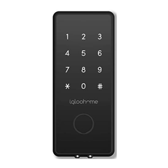
User Guide Lock Anatomy Front & Back Assembly Touch Screen Keypad Battery Cover Unlock LED Indicator Key hole Cover (Remove cover to access physical Thumbturn key unlock) 9V Jumpstart Clear Downlight LED... -
Page 20: Features
If battery power is drained, an external 9 Volt battery can be used to provide emergency power. The 2 contact points of the battery must be aligned with the 2 contact points on the Smart IoT Deadbolt for 2 seconds. - Page 21 Features Security / Alarms Activity Logs Keypad Security Lockout Be assured with an additional layer Entry via PIN codes and Bluetooth Key of security with the keypad lockout if will be logged in the app. the keypad is being tampered. User can configure number of incorrect Bluetooth key access logs are attempts to trigger lockout.
-
Page 22: Unlocking And Locking
Unlocking & Locking iglooworks App Bluetooth Unlock PIN Code Lock INB1 INB1 Last synced: a minute ago Moderate Change batteries in 9 months SYNC SYNC & UNLOCK Master PIN Lock Settings Physical Key Thumbturn Unlocking PIN Code Bluetooth Unlock Key in your PIN code and press On your app, click on the Bluetooth ‘Unlock’... -
Page 23: Lock Pairing & Provisioning
Lock Pairing & Provisioning Test Factory PIN Unlock 1234567890 In the factory mode (before pairing), the PIN to unlock is Register as a Admin/Owner a) Use the iglooworks management dashboard to send invitation of registeration to the user. b) Create the account via the link in the invitation and login. Pairing Pairing a) Click on the 3 dashes on the top left of the screen, and select [Pair New Lock]. -
Page 24: Iglooworks App Functions
iglooworks App Functions Setting Master PIN code Before proceeding, turn on your Bluetooth and ensure that you are within Bluetooth range of the lock. Go to the lock page and select [Master PIN]. Setting the Lock’s Beep Volume Go to the lock’s page, select [Lock Settings], select [Set beep volume], Choose your preferred volume from the choices provided, click on the Apply Changes button on the bottom of the page. -
Page 25: Lock Behaviour
Lock Behaviour Keypad Security Lockout After several incorrect PIN code attempts, the igloohome Smart Smart IoT Deadbolt keypad will be locked out and the security alarm will be triggered. Note: Physical key and Bluetooth Unlock can be used to unlock in this mode. -
Page 26: 9V Jumpstart Feature
9V Jumpstart Feature 1. Touch and hold the battery contacts against the 9V jumpstart pin on the lock and you will hear a series of beeps and the keypad will light up. 2. While holding the 9V battery to the jumpstart, key in your PIN code on the keypad followed by the ‘Unlock’... -
Page 27: Audio And Led Indications
Audio and LED indications Actions Indications Bluetooth Connection ‘Unlock’ icon flashes Blue Successfully Unlocked 4 fast ascending tones after unlocked Successfully Locked 1 long beep after lock is locked Incorrect PIN 4 short beeps Deleted PIN 3 sets of 4 short beeps Obstruction Alarm 6 sets of 4 short beeps Keypad Disabled... -
Page 28: Troubleshooting
• Use the spare QR sticker that is provided in the igloohome Smart IoT Deadbolt box. • Check the L/R toggle and ensure that it is at the correct side. • Refer to page 9 for details. - Page 30 For enquiries go to: igloohome.co/support...
Need help?
Do you have a question about the Smart IoT Deadbolt and is the answer not in the manual?
Questions and answers