Advertisement
Fluke Networks DSP-FTK Specs
Provided by www.AAATesters.com
FOM, FOS 850, FOS 1300, FOS 850/1300
Introduction
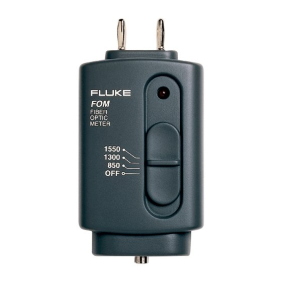
The Fiber Optic Power Meter (FOM) measures optical power on
fiber optic cables. An FOM indicates any power loss on tested
cables using any digital multimeter (DMM) or graphical
multimeter (GMM) that has a 10 MΩ input impedance, standard
diameter banana jacks, and mVdc capability. The Fiber Optic
Light Source (FOS) is used as a light source with the FOM or
other fiber optic meters.
Safety Information
All FOSs have been tested according to IEC 1010-1 and
IEC 825-1 and meet all requirements for a Class 1 LED Product.
To ensure the FOS is used safely, read the following warnings:
To avoid possible exposure to hazardous invisible LED
radiation and to prevent eye damage:
• Never look directly into the aperture (Figure 2) of the ST
connector.
• Do not open the case; no serviceable parts are inside.
Send the source to a authorized service center for
calibration or repair.
• Do not adjust or modify the source; LED sources may
exceed Class 1.
• Do not use magnification at the ST connector output.
• Caution - Use of controls or adjustments, or performance
of procedures other than those specified herein may
result in hazardous radiation exposure.
PN 200631 May 1996 Rev. 2, 2/97
©1996, 1997 Fluke Corporation. All rights reserved. Printed in U.S.A.
Fiber Optic Power Meter
Fiber Optic Light Source
P Warning P
Instruction Sheet
®
Advertisement
Table of Contents

Related Manuals for Fluke FOM


Summary of Contents for Fluke FOM
- Page 1 (DMM) or graphical multimeter (GMM) that has a 10 MΩ input impedance, standard diameter banana jacks, and mVdc capability. The Fiber Optic Light Source (FOS) is used as a light source with the FOM or other fiber optic meters. Safety Information All FOSs have been tested according to IEC 1010-1 and IEC 825-1 and meet all requirements for a Class 1 LED Product.
- Page 2 FOM Features DMM Plugs Battery Indicator LED FIBER OPTIC METER Function Switch 1550 1300 Input Connector (ST) aj1f.eps Figure 1. Fiber Optic Power Meter FOS Features FOS 850 Battery Indicator LED FIBER OPTIC SOURCE Function Switch Output Aperture Connector (ST) aj2f.eps...
- Page 3 FOS. Connect the launch and receive cables with a coupling (P/N 602810 or equivalent). Plug the FOM into the DMM or GMM with the red polarity indicator aligning with the voltage input. Select mVdc on the DMM.
- Page 4 Patch Panel Receive Cable Cable Under Test Launch Cable aj4f.eps Figure 4. Measuring Optical Loss Connect the launch and receive cables to cable under test; record the measurement. (Cables must be the same fiber type as the cable under test.) 10.
- Page 5 Replacing the Battery To replace the battery, refer to Figure 5. aj5f.eps Figure 5. Battery Replacement General Specifications Power Meter Specifications Output: 1 mV per 1 dB Input Connector Type: Fixed ST Photodetector Type: Germanium Application Range: 800 to 1600 nm Calibrated wavelengths: 850, 1300, and 1550 nm Acceptable fiber types...
- Page 6 For service information in the U.S.A., call 1-800-825-9810. Outside the U.S.A., contact an authorized service center. To locate an authorized service center, visit us on the World Wide Web: www.fluke.com or call Fluke using any of the phone numbers listed below: 1-800-443-5853 in U.S.A and Canada...
Need help?
Do you have a question about the FOM and is the answer not in the manual?
Questions and answers