Table of Contents
Advertisement
Quick Links
Advertisement
Table of Contents

Subscribe to Our Youtube Channel
Related Manuals for Fluke FEV150


Summary of Contents for Fluke FEV150
- Page 1 FEV150/FEV350 EV Charging Station Analyzer Users Manual 4/2024 Rev. 1, 5/2024 (English) ©2024 Fluke Corporation. All rights reserved. Specifications are subject to change without notice. All Product names are trademarks of their respective companies.
- Page 2 Fluke authorized resellers shall extend this warranty on new and unused products to end-user customers only but have no authority to extend a greater or different warranty on behalf of Fluke. Warranty support is available only if product is purchased through a Fluke authorized sales outlet or Buyer has paid the applicable international price.
-
Page 3: Table Of Contents
Table of Contents Title Page Introduction........................... Contact Fluke ..........................Safety Information........................The Product ..........................Features............................Display............................Main Menu ............................. Menu Controls..........................Test Menu ............................Set up a Test..........................Project List Menu ....................... Create a Project ......................10 Add a Project....................... 10 Delete a Project...................... - Page 4 FEV150/FEV350 Users Manual 6 mA RDC-DD Trip Test ....................31 Mains Voltage/Phase Sequence Test ................ 31 Nominal Voltage Test......................31 GFCI Trip Test ........................31 Control Pilot Test........................ 32 Proximity Pilot Test......................32 Error Test..........................32 Settings Menu ..........................33 Manual CP Menu..........................
-
Page 5: Introduction
The FEV350 allows for full installation certification in combination with a compatible multi- function tester (MFT) such as the Fluke 1664 FC. See the users manual for the MFT for instructions on how to set up, zero, and use the MFT. -
Page 6: Safety Information
General Safety Information is in the printed Safety Information document that ships with the Product and at www.fluke.com. More specific safety information is listed where applicable. A Warning identifies hazardous conditions and procedures that are dangerous to the user. A Caution identifies conditions and procedures that can cause damage to the Product or the equipment under test. - Page 7 Type 2 zero adapter (FEV350) Attach to a Type 2 plug to zero the connector or the test leads. Fluke 1664 FC Multi-function Use with the FEV350 for specific tests. See tester (MFT) Table TPAK Magnetic strap Use to attach the Product to a station with metal ...
-
Page 8: Features
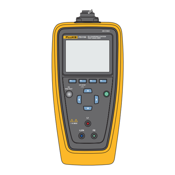
FEV150/FEV350 Users Manual Features Table 2 shows the features of the Product. Table 2. Features FEV150 FEV350 FEV150 FEV350 Item Description Function Plug connection port Use to connect a Type 1, Type 2, or Tesla type plug to the Product. -
Page 9: Display
Use to navigate the menu to highlight a selection or change a numerical value. Measurement terminals Use to connect test leads to the Product. FEV150: L1: Live wire L2/N: Neutral/second live wire for use with a split ... - Page 10 FEV150/FEV350 Users Manual Table 3. Display Item Description Function Name of the screen Name of the screen you are in. Time and date The time and date. Instruction subheader Shows the instructions for the screen. Screen content Main body of the screen.
-
Page 11: Main Menu
Use to manually select states and values to troubleshoot a Station. See Manual CP Menu. Troubleshoot GFCI Use to troubleshoot GFCI circuits. See Troubleshoot GFCI (FEV150) Menu. TruTest™ Software Use Bluetooth to connect the Product to TruTest software on a PC. See TruTest™ Software Menu... -
Page 12: Menu Controls
FEV150/FEV350 Users Manual Menu Controls Use the menu controls to navigate the menus, change settings, set up a project, and do a test. Table 5 lists the functions of the menu controls. Some menus contain a scroll bar on the right side to indicate there are additional options or rows. -
Page 13: Test Menu
EV Charging Station Analyzer Test Menu Table 5. Menu Controls Item Control Function Additional menu, Indicates there is another menu or test. test, or step With a submenu or option menu highlighted, push indicator (Select) to open the menu to adjust a setting, start a test, or to follow the on-screen instructions to connect the Product to an MFT or to TruTest software. -
Page 14: Create A Project
FEV150/FEV350 Users Manual Create a Project To create a project: 1. Highlight the Test menu, and push (Select). The Project List menu shows with Add Project highlighted. 2. Push (Select) to create a new project. Add a Project To add a project: 1. -
Page 15: Project Menu
EV Charging Station Analyzer Set up a Test 3. Push (...) and highlight Enter Code. 4. Push (Select). The Project List Enter Client and Site Code option menu shows. 5. Push to highlight a numerical field. 6. Push to increase or decrease a numerical value. 7. -
Page 16: Edit A Station
FEV150/FEV350 Users Manual 3. Push to highlight a station to copy. Note Fully configure the original station before you copy the station. 4. Push (Copy) to create a new station with the next sequential station number and the same configuration settings as the original station. A project may contain a maximum of 20 stations. -
Page 17: Configure A Station
FEV350. Table 6 is a list of the settings in the station configuration menu on the FEV150. Caution A setting that is incompatible with a previously selected setting causes a change to the previous setting. - Page 18 FEV150/FEV350 Users Manual Table 6. Station Configuration Menu (FEV150) Setting Description Connection Set the number of fixed cable or Tesla type connection points (the Points Connection Points) on the station. The maximum connection points on a station is two. The default setting is Connection Point 1.
- Page 19 EV Charging Station Analyzer Set up a Test Table 7. Station Configuration Menu (FEV350) Setting Description Station Type Set the station type. The default setting is Type 2 with cable. Type 1 with cable: L2 and L3 measurements are not available on tests. ...
- Page 20 FEV150/FEV350 Users Manual Table 7. Station Configuration Menu (FEV350) (cont.) Setting Description Earth Bond Limit Set the limit in ohms to use on an earth bond test. See Earth Bond Configuration (FEV350). The default setting is 0.3 . Test Point: Use with an MFT to do an Earth Bond Housing test on the ...
- Page 21 EV Charging Station Analyzer Set up a Test Table 7. Station Configuration Menu (FEV350) (cont.) Setting Description Fuse Type and Set the fuse type of the station. Then set the fuse rating of the fuse type. Rating The default fuse type is LS C. The default fuse rating is 20 A. Note If the fuse type or rating of the station does not show in the list, select the most appropriate fuse type or rating to use for tests.
-
Page 22: Earth Bond Configuration (Fev350)
FEV150/FEV350 Users Manual Table 7. Station Configuration Menu (FEV350) (cont.) Setting Description RCD Type Set the RCD type to enable the subtests in a 30 mA RCD Trip test. The default setting is Type A/F 30 mA. With the RCD type set to None, the 30 mA RCD Trip test does not show. - Page 23 EV Charging Station Analyzer Set up a Test To configure a station to do an Earth Bond test: 1. Go to Test > Project List. 2. Select a project, select a station, and highlight Earth Bond Limits. 3. Push (Select). The Earth Bond Limits menu shows.
-
Page 24: Connect The Plug
FEV150/FEV350 Users Manual Connect the Plug Figure 1 shows how to connect a plug to the Product. Figure 1. Connect the Plug FEV350... -
Page 25: Connect The Tpak Strap
EV Charging Station Analyzer Set up a Test Connect the TPAK Strap Warning Configure a station and do a PE Pre-Test and visual inspection test before you attach the TPAK strap to the station housing. See Do a Test. Figure 2 shows how to connect the TPAK magnetic strap to the Product. -
Page 26: Station And Connection Point Tests
FEV150/FEV350 Users Manual Station and Connection Point Tests Warning Configure a station and do a PE Pre-Test and visual inspection test before you touch the station housing or do any other station or connection point tests. Table 8 lists the Station and Connection Point tests the Product can do and notes which test requires an MFT to do the test. -
Page 27: Function Buttons In Tests
EV Charging Station Analyzer Function Buttons in Tests Function Buttons in Tests Table 9 shows some of the actions the function buttons may do. Not all functions are available in all tests. Table 9. Function Buttons in Tests Button Function Select: With a test highlighted, push to open the main menu of the test. -
Page 28: Symbols On Test Screens
FEV150/FEV350 Users Manual Figure 3. CP Stop FEV350 FEV350 CP Stop !2 s Symbols on Test Screens Table 10 describes the symbols that can be on a test screen. Table 10. Symbols on Test Screens Symbol Description FEV150 FEV350 Test visibility Indicates a Station or Connection Point test menu is not open. - Page 29 EV Charging Station Analyzer Symbols on Test Screens Table 10. Symbols on Test Screens (cont.) Symbol Description FEV150 FEV350 MFT required Indicates a test requires a compatible MFT. To connect the Product to an MFT, see Table Test status A test is not started, or a test is in process and not ...
- Page 30 FEV150/FEV350 Users Manual Table 10. Symbols on Test Screens (cont.) Symbol Description FEV150 FEV350 Earth bond test current indicator Indicates an earth bond test was taken with positive and negative test current. The Product shows the result of the one with the greatest resistance value.
-
Page 31: Do A Test
EV Charging Station Analyzer Do a Test Do a Test Warning Configure a station and do a PE Pre-Test and visual inspection test before you touch the station housing or do any other station or connection point tests. PE Pre-Test ... -
Page 32: Visual Inspection Test
FEV150/FEV350 Users Manual 6. Touch and hold a bare finger to the PE PRE-TEST sensor ( ) for 3 s. 7. Push (Next) to view the result. Warning If the result shows >50 V, stop the test immediately. There may be hazardous voltage present at the PE terminal and metal parts of the charging station. -
Page 33: How To Do Tests
EV Charging Station Analyzer Do a Test Table 11. Checklist Item Functionality Button Description Push to set a single item on the checklist to pass. Push and hold >2 s to set all items on the checklist to pass. Push to set a single item on the checklist to fail. Push and hold >2 s to set all items on the checklist to fail. -
Page 34: Earth Bond Tests
FEV150/FEV350 Users Manual 5. If necessary, highlight a test. 6. Push (Start) to start the test and overwrite existing results if 7. Follow the instructions on the display to do the test. If necessary while in a test, push (Back) to go back to the previous screen, or push (Stop) to stop the test and go back to the project and station test menu. -
Page 35: 30 Ma Rcd Trip Test
EV Charging Station Analyzer Do a Test 30 mA RCD Trip Test Trip Time: The test applies a ground fault or current imbalance to make sure a 30 mA RCD opens the circuit in the time listed in the standard based on the Mains System, Voltage Supply, and RCD Type set in the Station Configuration menu. -
Page 36: Control Pilot Test
The test converts the duty cycle to I . The Product saves up to 10 changes in CP state and output voltage L1/L2/L3 on the FEV350 and L1/L2 on the FEV150. With a test complete, the display shows a summary list of the events. -
Page 37: Settings Menu
Pair with MFT (FEV350) Follow the instructions on the display to pair the Product with a Fluke MFT. With more than one MFT on and in FC mode, the Product pairs with the MFT with the strongest signal. To pair with a specific MFT, turn off all MFTs except for the MFT you want to pair to. -
Page 38: Manual Cp Menu
Product. For the complete product specifications, see the FEV150/ FEV350 Product Specifications document on fluke.com. Language Use to select a language. Manual CP Menu Use the Manual CP screen to troubleshoot a station. The test uses the Voltage Supply value set in the Station Configuration menu. -
Page 39: Troubleshoot Gfci Menu
EV Charging Station Analyzer Troubleshoot GFCI Menu The Manual CP screen opens. The Product uses default settings to do a test automatically, and the results show on the display. The FEV150 default settings are: CP State: A Value: - ... -
Page 40: Trutest™ Software Menu
FEV150/FEV350 Users Manual 4. Push (Select) to set the selection. 5. Push (Start) to start the test. 6. If the GFCI trips, the seconds show on the display to indicate the length of time the GFCI took to trip. If the GFCI does not trip, shows on the display. -
Page 41: Battery Replacement
If this Product has an integral battery, put the entire Product in the electrical waste. All Product names are trademarks of their respective companies. Specifications are subject to change without notice. Fluke Corporation. All rights reserved. - Page 42 FEV150/FEV350 Users Manual...
Need help?
Do you have a question about the FEV150 and is the answer not in the manual?
Questions and answers