
Related Manuals for Xylem Bell & Gossett Autocirc e3-4 Series


Summary of Contents for Xylem Bell & Gossett Autocirc e3-4 Series
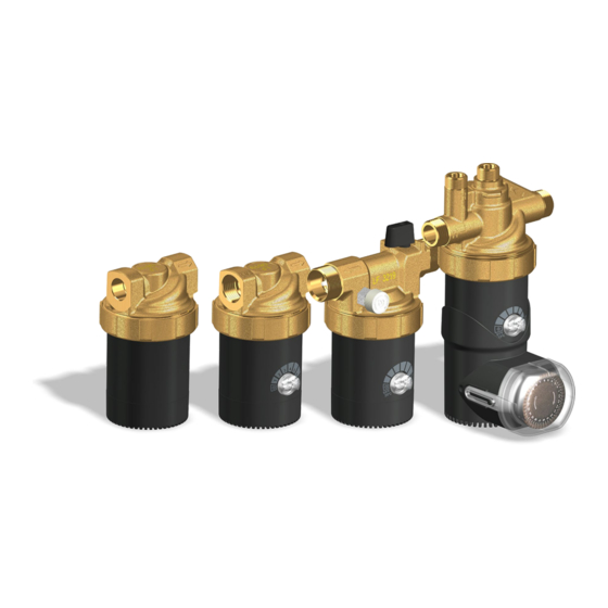
- Page 1 Installation, Operation and Maintenance Manual Series e -4 / e Instant hot water recirculating systems...
-
Page 2: Table Of Contents
en – Original Instructions Table of Contents Introduction and Safety ............................4 Introduction ..............................4 Safety ................................4 Danger levels and safety symbols ....................... 4 1.2.1 User Safety ..............................6 1.2.2 Handling and Storage ............................... 9 Handling of the packed unit ..........................9 Unit inspection upon delivery .......................... - Page 3 en – Original Instructions Fix speed models ............................33 5.6.1 Variable speed models ..........................33 5.6.2 Fix speed models with fix value temperature control ................33 5.6.3 Fix speed models with variable value temperature control ..............33 5.6.4 Autocirc pumps ............................34 5.6.5 LED light ..............................
-
Page 4: Introduction And Safety
The instructions and warnings of this manual apply to the standard unit as described in the sale documentation. Special version pumps may be supplied with supplementary instruction manuals. For situations not considered in the manual or in the sales document, contact Xylem or the Authorized Distributor. - Page 5 en – Original Instructions Danger levels Hazard level Indication DANGER: It identifies a dangerous situation which, if not avoided, causes serious injury, or even death. WARNING: It identifies a dangerous situation which, if not avoided, may cause serious injury, or even death.
-
Page 6: User Safety
en – Original Instructions 1.2.2 User Safety IMPORTANT SAFETY INSTRUCTIONS CAUTION: When installing and using this equipment, basic safety precautions should always be followed. Read, follow and save all these instructions! WARNING: To reduce the risk of injury, do not permit children to use this product unless they are closely supervised at all times. - Page 7 en – Original Instructions WARNING: Risk of electric shock Connect only to a branch circuit protected by a ground-fault circuit-interrupter (GFCI). Contact a qualified electrician if you cannot verify that the circuit is protected by a GFCI. The unit must be connected only to a supply circuit that is protected by a ground-fault circuit-interrupter (GFCI).
- Page 8 en – Original Instructions Electrical connections Electrical connections must be made by certified electricians in compliance with all international, national, state, and local regulations. Precautions before work Observe these safety precautions before you work with the product: • Make sure that you have a clear path of retreat. •...
-
Page 9: Handling And Storage
reject the goods, indicating the reason on the transport document. In both cases, promptly contact Xylem or the Authorized Distributor from whom the product was purchased. 2.2.2 Unpacking and inspection of the unit CAUTION: Cut and abrasion hazard Always wear personal protective equipment. -
Page 10: Unit Handling
en – Original Instructions Unit handling WARNING: Electrical hazard Holding the unit by the supply cord is strictly forbidden. WARNING: During handling, make sure to avoid injury to people and animals, and/or damage to property. Storage Storage of the packed unit The unit must be stored: •... -
Page 11: Technical Description
en – Original Instructions 3 Technical Description Designation Domestic hot water circulating pump. OEM applications For special OEM applications the pump has customized versions, which differ from the standard versions in one or more features of the followings: • Special software functions •... -
Page 12: Data Plate
en – Original Instructions Data plate Figure 1 No. Description No. Description Applied UL standard Technical code Rated voltage Nominal system pressure Frequency Maximum water temperature Input power Maximum water temperature for using with drinking water (NSF 61 classified) Serial number incl. manufacturing date Part number Model description Model description... -
Page 13: Names Of The Main Components And Accessories
en – Original Instructions Names of the main components and accessories Figure 3 Description Description End cap Pump housing Autocirc (code: BA) Control knob Fixing bracket Stator (pump motor) Screw 5/32”x1 9/16” (4x40 mm); 2 pcs. Cable gland Plastic anchor 1/4”x1 3/16” (6x30 mm); 2 pcs. -
Page 14: Intended Use
en – Original Instructions Intended use Circulating pump for domestic hot water systems. If hot water is not used for longer periods of time, the water in the hot water pipe cools off. Domestic hot water pumps (also called sanitary or drinking water circulating pumps) pump this cold water back into the water heater via a separate recirculation pipe, or directly into the cold water supply line (see Figure 5 and Figure 6 on page 19 and 20). - Page 15 Use a water conditioner if you have hard water. Hard water can cause scale build-up and eventually reduce the life of the pump and other system components. OEM applications For use with alternative circulating fluids contact Xylem or the Authorized Distributor. The liquids must be: • Clean •...
-
Page 16: Improper Use
en – Original Instructions Improper use WARNING: The unit was designed and built for the use described in section 3.6 Intended use on page 14. Any other uses are prohibited, as they could compromise the safety of the user and the efficiency of the unit itself. -
Page 17: Installation
en – Original Instructions 4 Installation Precautions Before starting, make sure that the safety instructions shown in section 1.2 Safety on page 4 have been fully read and understood. DANGER: Potentially explosive atmosphere hazard It is prohibited to start the unit in environments with potentially explosive atmospheres or with combustible dusts. -
Page 18: Hydraulic Connection
en – Original Instructions Hydraulic connection WARNING: All the hydraulic connections must be completed by a technician possessing the technical- professional requirements outlined in the current regulations. WARNING: Excessive system pressure hazard Piping must be sized to ensure safety at the maximum operating pressure. The maximum pressure value of the pump is listed on the data plate. - Page 19 en – Original Instructions • We recommend, that for pump models with pump housing code BT or BS, you install a ball shut-off valve before the pump at least, for future maintenance or repair works. • A properly installed system should include a method of automatically venting the air that enters the water supply line during use.
- Page 20 en – Original Instructions Figure 6 Description Description Tee fitting Circulating pump model BU Hot water return (recirculation) line Hose bib Hot water supply line Water heater Cold water supply line “Y” fitting Autocirc pumps • Select the sink under which the Autocirc pump is to be located (the sink where the hot water takes longest to arrive, which is usually the sink farthest from the water heater).
- Page 21 en – Original Instructions • Before starting installation work close the under sink hot and cold water riser shut-off valves and open the hot and cold water faucets/taps to relieve the water pressure. Close the water faucets/taps. NOTICE: In some older homes, the riser shut-off valves may be difficult to shut off completely, or maybe it is necessary to turn the valves into a different orientation.
-
Page 22: Installation
en – Original Instructions 4.3.2 Installation WARNING: Danger, system pressurized Before starting work, close the shut-off valves on the suction and discharge sides or drain the system. CAUTION: Install appropriate seals between the unit couplings and the piping system. WARNING: Hot water leakage hazard Pressurize the system slowly while checking for leaks at all joints with gaskets or solder connections. - Page 23 en – Original Instructions Permitted positions for recirculating pumps Figure 8 Autocirc pumps - Installation sequence 1. First read and follow the concerning instructions in section 4.3.1 Guidelines for the hydraulic system on page 20-21. 2. Fasten the Autocirc unit to the wall under the sink using the wall bracket provided in the Autocirc kit.
- Page 24 en – Original Instructions 3. Remove the existing flexible line connection to the hot and cold water faucet/tap threaded nipples. 4. Screw on the two existing 1/2” hose connections to the corresponding hot and cold sides of the pump housing (see Figure 10). Be sure not to “kink” these existing hose lines during bending which may prevent adequate flow and/or cause the valves to break.
-
Page 25: Rotation Of The Pump Motor
en – Original Instructions Figure 11 4.3.3 Rotation of the pump motor WARNING: Danger, system pressurized Before starting work, close the shut-off valves on the suction and discharge sides or drain the system. CAUTION: During the loosening of the screw ring from the pump housing, it is possible the leakage of residual very hot or cold liquid: pay attention to the risk of damages to persons. - Page 26 en – Original Instructions 1. Loosen the screw ring before installation. 2. Rotate the pump motor to the required installation position. 3. Tighten the screw ring. When installing the recirculating pump in a horizontal position, the timer shall point upwards. It may be turned in the range from 10:30 to 13:30 (±45°) at maximum, in order to maintain the ingress protection class (see Figure 13 on page 26).
-
Page 27: Electrical Connection
en – Original Instructions Electrical connection WARNING: Risk of electric shock Electrical connections are to be made by a qualified electrician in accordance with all applicable codes, ordinances and good practices. DANGER: Electrical hazard Disconnect and lock out the power before making electrical connections. Before starting work, check that the unit cannot restart, even unintentionally. -
Page 28: Guidelines For Electrical Connection
en – Original Instructions 4.4.2 Guidelines for electrical connection • Check that the mains voltage and frequency match the specifications on the data plate. • Protect the supply cord from high temperatures, vibrations, collisions and abrasions. • Check that the power supply line is provided with a short circuit protection device of appropriate size. -
Page 29: Guidelines For Timer Connection
en – Original Instructions 5. Cable installation: • Insert the cable through the threaded hole into the motor housing. • Push the lever of the terminal block with a flat screw driver and get each stripped core into the proper hole. •... -
Page 30: Use And Operation
en – Original Instructions 5 Use and Operation Precautions WARNING Make sure that the discharged liquid cannot cause damage to persons or things. WARNING: Electrical hazard Check that the unit is properly connected to the mains power supply. WARNING: Hot surface hazard Motor housing may be very hot. -
Page 31: Air Purge
en – Original Instructions Air purge After filling the system with liquid, any residual air shall be removed from the pump housing. To aid this effort, the standard pump models with control knob are equipped with a built-in air purge function. For activation, turn the knob to the right end position for 5 seconds (the air purge symbol is shown on the scale, see Figure 15). - Page 32 en – Original Instructions 3. Program the on/off times by pulling the tabs outward until flushing with the dial face for the pump to operate on during selected time periods. Push the tabs inward, one step behind the dial face for the pump to remain off during the selected time periods.
-
Page 33: Operation Modes
en – Original Instructions Operation modes According to the chart in section 3.2 Integrated features and functions on page 11, the different pump versions have different integrated functions, thus operation modes. 5.6.1 Fix speed models These pumps are not equipped with a control knob; run on a constant speed if energized, until reaching the power limit, then the speed may be reduced. -
Page 34: Autocirc Pumps
en – Original Instructions 5.6.5 Autocirc pumps These pumps are the timer controlled versions of the fix speed models with temperature control, equipped with a special pump housing for simple under sink installation. There are two models: • e -4F/BAPQC: Fix value temperature controlled (for operation details see section 5.6.3 on page 33). -
Page 35: Dry Run Protection
en – Original Instructions 5.6.8 Dry run protection This function is available only for some fix speed models. This algorithm protects the unit from dry running during normal operation. The pump monitors the input power level and if it drops below a preset value for a specified time interval, the pump starts a sequence with 9 cycles of 30 s on and 60 s off, then a 10-minute pause and so on, until the expected power level restored and the pump can continue the normal operation. -
Page 36: Maintenance
Maintenance • Check the integrity of the supply cord every 6 months of operation; if the cable is damaged contact Xylem or the Authorized Distributor for its replacement. Do not use the unit with damaged cord. • Carefully clean the unit from outside. -
Page 37: Autocirc Pumps
en – Original Instructions Autocirc pumps If you are away from home for extended periods of time (2 weeks or more) you may choose to turn the system off (slide the timer switch to the "Off" position) as there is no need to maintain hot water in the supply line when no one is home to enjoy this convenience. -
Page 38: Troubleshooting
Observe the safety requirements in section 5 Use and Operation on page 30 and section 6 Maintenance on page 36. WARNING: If a fault cannot be corrected or is not mentioned, contact Xylem or the Authorized Distributor. Error signals The pump is equipped with self-diagnostics and malfunction detection. Defects detected by the pump system are signaled to the user with alternating short and long LED light flashes. -
Page 39: Noise In The System
en – Original Instructions Noise in the system The pump should be virtually noiseless during operation. The rotor may make a brief but hardly perceptible fluttering noise immediately after the pump is turned off. During normal operation, an occasional air bubble may pass through the pump housing causing a momentary gurgling noise. -
Page 40: Technical Information
Relative humidity of the air Maximum 95 % at 122 °F (50 °C) NOTICE: In the event, that temperature and humidity exceed the indicated limits, contact Xylem or the Authorized Distributor. NOTICE: To avoid condensation in the stator or in the electronics, the liquid temperature must be higher than the ambient temperature. -
Page 41: Mechanical Characteristics
en – Original Instructions Mechanical characteristics Ingress protection class Without timer: IP 44 With timer: IP 42 Maximum working pressure UL 778 certified models: 145 psi (1.0 MPa) UL 1081 certified models: 29 psi (0.2 MPa) Sound pressure level ≤ 40 dB(A) Dimensions and weights - _ _ /BS _ _ _ - _ _ /BT _ _ _... - Page 42 en – Original Instructions - _ _ /BU _ _ _ -4V/BAP _ C Models Weight [lb (kg)] - _ V/BUPYZ-01 - _ F/BUPQZ-01 - _ F/BUPRZ-01 - _ F/BUPYZ-01 2.6 (1.2) - _ V/BUXYZ-01 - _ F/BUXQZ-01 - _ F/BUXRZ-01 - _ F/BUXYZ-01 2.2 (1.0) - _ V/BUPYC-01 e...
-
Page 43: Hydraulic Curves
en – Original Instructions Hydraulic curves -4F/BS _ _ Z & e -4F/BT _ _ Z -4V/BS _ _ Z & e -4V/BT _ _ Z -4F/BU _ _ Z -4V/BU _ _ Z Installation, Operation and Maintenance Manual... - Page 44 en – Original Instructions -6F/BS _ _ Z & e -6F/BT _ _ Z -6V/BS _ _ Z & e -6V/BT _ _ Z -6V/BU _ _ Z -4F/BAP _ C Installation, Operation and Maintenance Manual...
-
Page 45: Oem Models
en – Original Instructions OEM models For special OEM (Original Equipment Manufacturer) applications the pump has customized versions, which differ from the standard trade versions in some features. An individual PSS (Product Specification Sheet) document is issued for each of these versions including the hydraulic curve and the technical details highlighting the difference from the standard versions. -
Page 46: Disposal
en – Original Instructions 9 Disposal Precautions WARNING: The unit must be disposed of through approved companies specialized in the identification of different types of materials (steel, copper, plastic, etc.). WARNING: It is prohibited to dispose of lubricating fluids and other hazardous substances in the environment. -
Page 47: Warranty
en – Original Instructions 10 Warranty Commercial warranty For goods sold to commercial buyers, Seller warrants the goods sold to Buyer hereunder (with the exception of membranes, seals, gaskets, elastomer materials, coatings and other "wear parts" or consumables all of which are not warranted except as otherwise provided in the quotation or sales form) will be (i) be built in accordance with the specifications referred to in the quotation or sales form, if such specifications are expressly made a part of this Agreement, and (ii) free from defects in material and workmanship for a period of twelve (12) from the date... - Page 48 en – Original Instructions Limited consumer warranty For goods sold for personal, family or household purposes, Seller warrants the goods purchased hereunder (with the exception of membranes, seals, gaskets, elastomer materials, coatings and other "wear parts" or consumables all of which are not warranted except as otherwise provided in the quotation or sales form) will be free from defects in material and workmanship for a period of twelve (12) from the date of installation or twenty-four (24) months from the product date code, whichever shall occur first, unless a longer period is provided by law or is specified in the...
- Page 49 Xylem Inc. 8200 N. Austin Avenue Morton Grove, Illinois 60053 Phone: (847) 966-3700 Fax: (847) 965-8379 www.xyleminc.com/brands/bellgossett Bell & Gossett is a trademark of Xylem Inc. or one of its subsidiaries. © 2020 Xylem Inc. 671075217EN rev. A ed. 08/2020...
Need help?
Do you have a question about the Bell & Gossett Autocirc e3-4 Series and is the answer not in the manual?
Questions and answers