
Related Manuals for Alpha-InnoTec LW Series


Summary of Contents for Alpha-InnoTec LW Series
- Page 1 Air/Water Heat Pumps Indoor installation Operating Manual LW 300(L) 83031300dUK...
-
Page 2: Table Of Contents
Table of contents 17 Insulate hydraulic connections About this operating manual ....16 ...... 3 Validity ............3 18 Set the overflow valve ........ 17 Reference documents ....... 3 19 Commissioning ..........17 Symbols and markings ......3 20 Maintenance Contact ............4 .......... -
Page 3: About This Operating Manual
About this operating manual 1.3 Symbols and markings This operating manual is part of the unit. Identification of warnings ► Before working on or with the unit read the Symbol Meaning operating manual carefully and follow it for all activities at all times, especially the warnings and Safety-relevant information. -
Page 4: Contact
Only qualified, skilled personnel is able to carry out are kept up-to-date: the work on the unit safety and correctly. Interference by unqualified personnel can cause life-threatening ● Germany: www.alpha-innotec.de injuries and damage to property. ● www.alpha-innotec.com ► Ensure that the personnel is familiar with the local regulations, especially those on safe and hazard- aware working. -
Page 5: Disposal
Injury due to moving parts Improper action ► Switch device on only with air ducts and weather Requirements for minimum scale and corrosion and/or rain louvres fitted. damage in hot water heating systems: ● Proper planning, design and commissioning Injuries and environmental damage due to ●... -
Page 6: Description
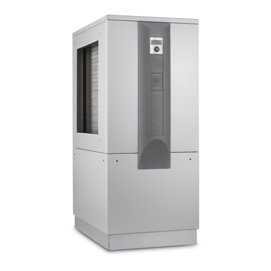
Description 3.2 Layout Basic components 3.1 Delivery condition NOTE This section essentially names the compo- nents relevant for fulfilling the tasks described in this operating manual. The following figure shows an LW 300 unit. The positions of the fan and the evaporator are reversed in the L version. Unit with a completely hermetically enclosed compressor, all safety-related components for monitoring of the cooling circuit, integrated... -
Page 7: Accessories
Operation and care Nameplates Nameplates are attached to the following places on the unit when it is delivered: NOTE ● outside: On the lower facing panel of the fan side The unit is operated via the control unit of the (for unit variant L: evaporator side) heating and heat pump controller ( Oper- ●... -
Page 8: Scope Of Supply, Storage, Transport And Installation
Scope of supply, storage, 5.3 Transport transport and installation Notes on safe transport The unit is heavy ( “Technical data / scope of sup- IMPORTANT ply”, page 20). There is a risk of injuries or damage Damage to the housing and the unit components to property if the unit falls or overturns. - Page 9 Remove lower facing panels on the fan side of the unit. To do so, loosen quick-release screws. Turn counter-clockwise 90°. Pull lower facing panel upwards and outwards, detach and set securely to the side. Example: Removing the upper facade on the operating side At the fan, thread the two guide rods supplied through the metal tab and fan.
-
Page 10: Installation
5.4 Installation Push the fan in the direction of the evaporator up to the top metal tab inside the unit. CAUTION In the air outlet area the air temperature is approx. 5 K below the ambient temperature. Under certain climatic conditions, an ice lay- er can therefore form in the air outlet area. -
Page 11: Installation Of Air Ducting
Installation of hydraulic system NOTE The noise emissions of the heat pumps ► Flush the heating circuit thoroughly before con- must be taken into account in the respective necting it to the heating system. installation plans for air/water heat pumps. The respective regional regulations must be IMPORTANT observed. -
Page 12: Pressure Relief
Buffer tank Condensate discharge The outlet for the heating water safety valve and the The hydraulic connection of the heat pump requires a condensate from the air must be drained off in accord- buffer tank in the heating circuit. ance with the respective applicable standards and reg- Required volume of the buffer tank: ulations. Discharging the condensate and the safety ... -
Page 13: Electrical Installation
13 Electrical installation Lead power cable, power cable for circulating pumps and cable for external temperature sensor through the rubber sockets on the facing panel in 13.1 Establishing the electrical the unit. connections 3.1. Cut out the rubber grommets on the lower facing of the water connection side. -
Page 14: Installation Of The Control Unit
14 Installation of the control unit Push the control unit down until it locks into posi- tion. Situated at different heights in the upper facade of the operating side of the unit are recesses (each with 4 re- cesses) for the fastening of the control unit: Stick the heating and heat pump regulator’s con- trol cable into the right bushing on the bottom of the control unit. -
Page 15: Installation And Removal Of The Screen
15 Installation and removal of the Beginning first on one side and moving upwards, lock the screen’s snap-in lugs in place in the screen slots provided on the facade. 15.1 Installing the screen NOTE The screen is provided at the time of delivery so that the control unit may be inserted in the upper recesses of the facade facade of the operating side of the unit. -
Page 16: Flushing, Filling And Venting
16 Flushing, filling and venting 16.2 Flush, fill and vent the heating circuit 16.1 Heating water quality Outlet pipe of the safety valve is connected. Ensure that the set pressure of the safety valve is NOTE not exceeded. ● For detailed information refer, among Vent system at the respective highest point. other things, to the VDI Guidelines 2035 “Vermeidung... -
Page 17: Set The Overflow Valve
18 Set the overflow valve 19 Commissioning NOTE CAUTION The unit may only be started up if the air ● The activities in this section are only necessary for the integration of storage ducts, weather and/or rain louvres have tanks in series been installed and the facing panels are closed. -
Page 18: Maintenance
20 Maintenance Check evaporator and condensate pan and clean if required Unit is safely disconnected from the power sup- NOTE ply and secured against being switched back on We recommend that you conclude a mainte- again. nance agreement with an accredited heating company. -
Page 19: Faults
21 Faults ► Read out the cause of the fault via the diagnostics program of the heating and heat pump controller. ► Contact the local partner of the manufacturer or the factory’s customer service. Have the fault message and unit number to hand. “Nameplates“, page 7 22 Dismantling and disposal 22.1 Dismantling... -
Page 20: Technical Data / Scope Of Supply
Technical data / scope of supply LW 300(L) Performance data Values in brackets: (1 Compressor) LW 300(L) Heating capacity | COP for A7/W35 acc. to EN14511 kW | COP 32,50(19,78)|3,80(4,04) for A7/W45 acc. to EN14511 kW | COP 33,64(18,99)|3,20(3,23) for A2/W35 acc. to EN14511 kW | COP 29,67(16,97)|3,41(3,52) for A10/W35 acc. -
Page 21: Performance Curves
LW 300(L) Performance curves Qh (kW) Temp„ (°C) Pe (kW) 35°C 1VD 55°C 1VD 35°C 2VD 55°C 2VD Temp„ (°C) Temp„ (°C) ∆p (bar) Temp” (C°) 0,125 0,100 0,075 0,050 0,025 ”p∆ 0,000 10,0 Temp„ (°C) “” (m³/h) 823310a Legende: UK823310a Volume flow heating water “”... -
Page 22: Dimensional Drawings
Dimensional drawings LW 300 Keys: UK819357c All dimensions in mm. Front view Side view from left Side view from right Rear view Air direction Pos. Pos. Designation Designation Dim. LW 300 Dim. LW 300 Control unit Hot water outlet (flow) R 6/ 4 " Hot water inlet (return) R 6/ 4 "... - Page 23 LW 300L Dimensional drawings Keys: UK819358c All dimensions in mm. Front view Side view from left Side view from right Rear view Air direction Pos. Pos. Designation Designation Dim. LW 300L Dim. LW 300L Control unit Hot water outlet (flow) R 6/ 4 " Hot water inlet (return) R 6/ 4 "...
-
Page 24: Installation Plans
Installation plan V1 LW 300(L) 1020 ≥800 ≥800 > 2965 Legende: 819337 Pos. Bezeichnung Technische Änderungen vorbehalten. Zubehör: Wanddurchführung 1000x1000x420 Alle Maße in mm. Zubehör: Luftkanal 900x900x1000 Zubehör: Luftkanalbogen 900x1050x1450 Pos. Bezeichnung Maß Einbau über Erdgleiche: Keys: UK819337a-1 All dimensions in mm. Bei Fertigwandstärke 240 bis 320 2340 Zubehör: Wetterschutzgitter 1045x1050... -
Page 25: Installation Plan V2
LW 300(L) Installation plan V2 1020 ≥800 ≥800 > 2965 Legende: 819337 Pos. Bezeichnung Technische Änderungen vorbehalten. Zubehör: Wanddurchführung 1000x1000x420 Alle Maße in mm. Zubehör: Luftkanal 900x900x1000 Keys: UK819337a-2 All dimensions in mm. Zubehör: Luftkanalbogen 900x1050x1450 Pos. Bezeichnung Maß Einbau über Erdgleiche: Pos. -
Page 26: Installation Plan V3
Installation plan V3 LW 300(L) 2023 1020 1020 ≥800 ≥800 >3430 Legende: 819337 Pos. Bezeichnung Keys: UK819337a-3 All dimensions in mm. Technische Änderungen vorbehalten. Zubehör: Wanddurchführung 1000x1000x420 Alle Maße in mm. Zubehör: Luftkanalbogen 900x1050x1450 Dim. Dim. Pos. Pos. Designation Designation Einbau über Erdgleiche: Pos. -
Page 27: Installation Plan V4
LW 300(L) Installation plan V4 3023 1020 1020 ≥800 ≥800 > 4430 Legende: 819337 Pos. Bezeichnung Technische Änderungen vorbehalten. Zubehör: Wanddurchführung 1000x1000x420 Alle Maße in mm. Zubehör: Luftkanal 900x900x1000 Zubehör: Luftkanalbogen 900x1050x1450 Pos. Bezeichnung Maß Einbau über Erdgleiche: Bei Fertigwandstärke 240 bis 320 Zubehör: Wetterschutzgitter 1045x1050 Keys: UK819337a-4... -
Page 28: Hydraulic Integration
Separation buffer tank LW 300(L) Subject to change without notice | 83031300dUK | ait-deutschland GmbH... -
Page 29: Keys Hydraulic Integration
Subject to change without notice | 83031300dUK | ait-deutschland GmbH... -
Page 30: Terminal Diagram
Terminal diagram LW 300(L) 3~N/PE/400V/50Hz 3~N/PE/400V/50Hz 3~PE/400V/50Hz 1~N/PE/230V/50Hz B10 A ZW2/SST Subject to change without notice | 83031300dUK | ait-deutschland GmbH... - Page 31 LW 300(L) Circuit diagram 1/3 X10:L1 X10:L2 X10:L3 X10:PE !!! KEINE ÜBERSETZUNG !!! Subject to change without notice | 83031300dUK | ait-deutschland GmbH...
- Page 32 Circuit diagram 2/3 LW 300(L) X10:L X10:N X10:PE X10:2 X10:3 X10:4 !!! KEINE ÜBERSETZUNG !!! Subject to change without notice | 83031300dUK | ait-deutschland GmbH...
-
Page 33: Circuit Diagrams
LW 300(L) Circuit diagram 3/3 !!! KEINE ÜBERSETZUNG !!! Subject to change without notice | 83031300dUK | ait-deutschland GmbH... - Page 34 Subject to change without notice | 83031300dUK | ait-deutschland GmbH...
-
Page 35: Ec Declaration Of Conformity
Subject to change without notice | 83031300dUK | ait-deutschland GmbH... - Page 36 GmbH Industriestraße 3 D-95359 Kasendorf E info@alpha-innotec.de W www.alpha-innotec.de alpha innotec – an ait-deutschland GmbH brand...
Need help?
Do you have a question about the LW Series and is the answer not in the manual?
Questions and answers