
Related Manuals for Alpha-InnoTec LW 140


Summary of Contents for Alpha-InnoTec LW 140
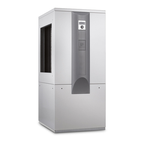
- Page 1 Air/Water Heat Pumps Indoor installation Operating Manual LW 140(L) – LW 251(L) 83054400fUK...
-
Page 2: Please Read First
Please read first Symbols This operating manual provides important informa- The following symbols are used in the operating man- tion on the handling of the unit. It is an integral part of ual. They have the following meaning: the product and must be stored so that it is accessi- ble in the immediate vicinity of the unit. -
Page 3: Table Of Contents
11 Area of utilisation ........... 6 Dimensional drawings ........31 12 Heat quantity recording ....... 7 LW 140 – LW 180 ..........31 LW 140L – LW 180L ......... 32 13 Operation ............7 LW 251 ............. 33 14 Care of the unit .......... -
Page 4: Intended Use
Intended use Safety and Security The unit may be used only for the intended purpose. The unit is safe to operate when used for its intended That means: purpose. The construction and design of the unit conform to current state-of-the-art standards, all ●... - Page 5 DANGER WARNING Danger of fatal injury due to electric cur- Switch on unit only if air ducts are mount- rent! ed on the unit. Electrical connections may be installed on- Take measures on the fan side to pre- ly by qualified electricians. vent injuries from the rotating fan (above- Before opening the unit, disconnect the ground air duct discharge: below-ground...
-
Page 6: Contact
The refrigerator extracts heat from foods, which is re- ● Germany: www.alpha-innotec.de leased into the room through fins on the back. ● EU: www.alpha-innotec.com The heat pump extracts heat from our environment: air, earth or ground water. -
Page 7: Heat Quantity Recording
12 Heat quantity recording 14 Care of the unit In addition to the proof of the unit's efficiency, EE- The outer surfacesof theunit can be cleaned with a WaermeGalso meets the demand for a heat quantity damp cloth and household cleaning products. recording (hereafter refered to as HQR). -
Page 8: Scope Of Delivery
15 Scope of delivery Inspect delivery for outwardly visible signs of damage. Check to make sure that delivery is complete. Example of scope of delivery: Any defects or incorrect deliveries must be View 1: claimed immediately. NOTE Note the model. Check the air blow-out direc- tion of the unit. -
Page 9: Installation Location
16.1 Installation location 16.2 Transport to installation location To prevent damage during transport, always transport IMPORTANT the unit to final installation location in its original pack- aging, using a lifting truck. Install the unit only indoors. Installation room and space requirements NOTE You can underpin the LW 251(L) using a lift- NOTE... - Page 10 On the back of the unit, remove the sealing grom- met. (not possible with the LW 251(L)) The LW 140(L) and LW 180(L) units can be lifted with " and/or 1" pipes (provided by customer) that are suitable for the weight of the respective unit. Special holes are provided in the frame for this purpose.
- Page 11 Retractable ventilator Pull lower facing panel upwards and outwards, detach and set securely to the side. In order to allow the unit to be easily transported through tight cellar spaces and narrow doorways and/ or hallways, the ventilator retracts approx. 10 cm into the body of the unit.
-
Page 12: Installation
Lower the unit at the installation location. Make Then, on both sides, hook the guide rods in the sure that the frame of the unit is in full contact with keyhole slot pattern of the upper metal tab inside the underlying surface and the unit is positioned the unit. - Page 13 Wall duct(s) assembly Stabilise the wall duct from the inside using the chipboard included with delivery. Remove the parts necessary for the assembly of the wall duct(s) from their respective boxes. Install the wall duct in the masonry from the Next, interlock the 2 pieces of the wall duct(s) house exterior.
- Page 14 Air ducts assembly NOTE After the other end of the air duct has been Remove the parts necessary for the assembly of secured to the heat pump, close the opening the air duct(s) from their respective boxes. between the wall duct and the air duct using the bentonite waterstop tape included with delivery.
- Page 15 Screen frame assembly Position the wire mesh grille in the assembly frame. Screw the screen frame to the wall ducts on both the air intake and output sides. Set the weather / rain guards on the assembly frame in the wall duct and screw down. NOTE The screen frame has no function, it is in- cluded solely to provide an optically attractive...
-
Page 16: Installation / Connection To Heating Circuit
16.5 Installation / connection to Install shut-off devices for the hot water outflow (forward flow) and hot water inflow (return flow) on heating circuit the heat pump side. IMPORTANT NOTE Connect the unit to the heating circuit accord- During installation of the shut-off devices, the ing to the hydraulic diagram for the respec- liquefier of the heat pump can be rinsed, if tive model. -
Page 17: Pressure Relief
20 Circulating pumps IMPORTANT Guide the pre-mounted hose in the unit for condensate discharge in the interior of the IMPORTANT unit as a siphon, as shown in the illustration. Always note the model. Discharge of the condensate into the sewage system Do not use regulated circulating pumps. -
Page 18: Electrical Connections
23 Electrical connections Lead 230 V power cable, power cable for circu- lating pumps and cable for external temperature sensor through the rubber sockets on the facing Observe the following when performing all work: panel in the unit. 3.1. Cut out the rubber sockets on the facing panel. DANGER Danger of fatal injury due to electric cur- ... -
Page 19: Rinsing, Filling And Bleeding The System
24 Rinsing, filling and bleeding For further information, see the adhesive label on the electric heating element the system NOTE The control element of the heat and heat IMPORTANT pump regulator can be connection with a The system must be absolutely free from air computer or network using an network ca- before commissioning. -
Page 20: Insulating The Hydraulic Connections
26 Installation of the control Monitoring element Analytical recording and monitoring of the relevant water values and the added active conditioning substances is of decisive importance. Therefore, they Situated at different heights in the front facade of the should be monitored regularly using appropriate water unit are recesses (each with 4 recesses) for the fas- test equipment. -
Page 21: Installation And Removal Of The Screen
27 Installation and removal of the Push the control element down until it locks into position. screen 27.1 Installing the screen NOTE The screen is provided at the time of delivery so that the control element may be inserted in the upper recesses of the front facade. -
Page 22: Set The Overflow Valve
28 Set the overflow valve Beginning first on one side and moving upwards, lock the screen's snap-in lugs in place in the slots provided on the front of the facade. REMARQUE The activities in this section are only neces- sary for in-line tank integration. Complete the worksteps quickly, otherwise the maximum return temperature can be ex- ceeded and the heat pump switches to high-... -
Page 23: Commissioning
29 Commissioning The heat pump system is commissioned by cus- tomer service personnel authorised by the manu- facturer. There is a fee for starting up! DANGER The unit may only be started up if the air ducts, weather and/or rain louvres have 30 Maintenance of the unit been installed and the facing panels are closed. -
Page 24: Annual Maintenance
31 Malfunctions 30.1 Annual maintenance ► Determine the quality of the heating water by anal- In the event of a malfunction, you can detect the cause ysis. In the event of deviations from the specifica- of the malfunction via the diagnostic program of the tions, take suitable measures without delay. -
Page 25: Dismantling
32 Dismantling DANGER Danger of fatal injury due to electric current! Electrical connections may be installed only by qualified electricians. Before opening the unit, disconnect the system from the power supply and secure it from being switched back on! WARNING Only qualified heating or cooling system technicians are allowed to remove the unit from the system. -
Page 26: Technical Data / Scope Of Delivery
Technical data / scope of delivery Model designation Heat pump type Brine/water ı Air/water ı Water/water • applicable ı — not applicable Installation location Indoors ı Outdoors • applicable ı — not applicable Conformity Performance data Heating capacity/COP at 2 Compressors kW ı... - Page 27 LW 140(L) LW 180(L) LW 251(L) — ı • ı — — ı • ı — — ı • ı — • ı — • ı — • ı — • • • — 19.6 ı 3.9 27.3 ı 3.9 14.4 ı...
-
Page 28: Performance Curves
Ä Ä n n d d . . / / Ä Ä . . M M . . / / E E r r s s t t e e l l l l e e r r / / D D a a t t u u m m LW 140 (L;A) Seite: 1/1 - / PEP028-2009 / Opel / 16.03.10... - Page 29 Performance curves LW 180(L) Qh (kW) Temp„ (°C) Pe (kW) 35°C 1VD 50°C 1VD 35°C 2VD 50°C 2VD Temp„ (°C) Temp„ (°C) ∆p (bar) 0,4000 0,3000 0,2000 p∆” 0,1000 0,0000 “” (m³/h) 823155 Legende: DE823129L/170408 “” Volumenstrom Heizwasser Temp„ Temperatur Wärmequelle Heizleistung Leistungsaufnahme Coefficient of performance / Leistungszahl...
- Page 30 LW 251(L) Performance curves Qh (kW) Temp„ (°C) Pe (kW) 35°C 1VD 50°C 1VD 35°C 2VD 50°C 2VD Temp„ (°C) Temp„ (°C) ∆p (bar) 0,4000 0,3500 0,3000 0,2500 0,2000 0,1500 0,1000 p∆” 0,0500 0,0000 “” (m³/h) 823156a Legende: DE823129L/170408 “” Volumenstrom Heizwasser Temp„...
-
Page 31: Dimensional Drawings
LW 140 – LW 180 Dimensional drawings Legend: UK819355b All dimensions in mm. Front view Side view from left Side view from right Rear view Air direction Item Item Designation Designation Control panel Hot water outlet (flow) G 5/4" DIN ISO 228 Hot water inlet (return) G 5/4"... -
Page 32: Lw 140L - Lw 180L
Dimensional drawings LW 140L – LW 180L 4x M8 1780 1620 1578 4x M8 1620 1578 Legend: UK819356a All dimensions in mm. Front view Side view from left Side view from right Rear view Air direction Item Item Designation Designation Control panel Hot water outlet (flow) G 5/4"... - Page 33 LW 251 Dimensional drawings 4x M8 1887 1763 1718 4x M8 1763 1718 Legende: D819357b Legend: UK819357b Technische Änderungen vorbehalten. Alle Maße in mm. All dimensions in mm. Front view Vorderansicht Seitenasicht von links Side view from left Seitenansicht von rechts Side view from right Rückansicht Rear view...
- Page 34 Dimensional drawings LW 251L 4x M8 1887 1763 1718 4x M8 1763 1718 Legende: D819358b Technische Änderungen vorbehalten. Alle Maße in mm. Legend: UK819358b Vorderansicht Seitenasicht von links All dimensions in mm. Seitenansicht von rechts Rückansicht Front view Luftrichtung Side view from left ÄM 999/2010 Side view from right ÄM 999/2010...
-
Page 35: Installation Plans
LW 140(L) – LW 180(L) Installation plan version 1 1020 ≥800 ≥800 > 2965 Item Item Designation Designation Dim. Dim. Legende: UK819336c-1 With finished wall thickness 240 to 320 2340 All dimensions in mm. With finished wall thickness 320 to 400... -
Page 36: Installation Plan Version 2
Installation plan version 2 LW 140(L) – LW 180(L) 1020 ≥800 ≥800 > 2925 Item Item Designation Designation Dim. Dim. Legende: UK819336c-2 With finished wall thickness 240 to 320 2340 All dimensions in mm. With finished wall thickness 320 to 400... -
Page 37: Installation Plan Version 3
LW 140(L) – LW 180(L) Installation plan version 3 2023 1020 1020 ≥800 ≥800 >3430 Item Item Designation Designation Dim. Dim. Legende: UK819336c-3 With finished wall thickness 240 to 320 All dimensions in mm. With finished wall thickness 320 to 400... -
Page 38: Installation Plan Version 4
Installation plan version 4 LW 140(L) – LW 180(L) 3023 1020 1020 ≥800 ≥800 > 4430 Dim. Dim. Item Item Designation Designation Legende: UK819336c-4 With finished wall thickness 240 to 320 All dimensions in mm. With finished wall thickness 320 to 400... -
Page 39: Lw 251(L)
LW 251(L) Installation plan version 1 1020 ≥800 ≥800 > 2965 Legende: 819337 Pos. Bezeichnung Technische Änderungen vorbehalten. Zubehör: Wanddurchführung 1000x1000x420 Alle Maße in mm. Zubehör: Luftkanal 900x900x1000 Zubehör: Luftkanalbogen 900x1050x1450 Pos. Bezeichnung Maß Einbau über Erdgleiche: Legend: UK819337a-1 All dimensions in mm. Bei Fertigwandstärke 240 bis 320 2340 Zubehör: Wetterschutzgitter 1045x1050... -
Page 40: Installation Plan Version 2
Installation plan version 2 LW 251(L) 1020 ≥800 ≥800 > 2965 Legende: 819337 Pos. Bezeichnung Technische Änderungen vorbehalten. Zubehör: Wanddurchführung 1000x1000x420 Alle Maße in mm. Zubehör: Luftkanal 900x900x1000 Legend: UK819337a-2 All dimensions in mm. Zubehör: Luftkanalbogen 900x1050x1450 Pos. Bezeichnung Maß Einbau über Erdgleiche: Item Item... -
Page 41: Installation Plan Version 3
LW 251(L) Installation plan version 3 2023 1020 1020 ≥800 ≥800 >3430 Legende: 819337 Pos. Bezeichnung Technische Änderungen vorbehalten. Zubehör: Wanddurchführung 1000x1000x420 Legend: UK819337a-3 All dimensions in mm. Alle Maße in mm. Zubehör: Luftkanalbogen 900x1050x1450 Einbau über Erdgleiche: Item Item Designation Designation Dim. -
Page 42: Installation Plan Version 4
Installation plan version 4 LW 251(L) 3023 1020 1020 ≥800 ≥800 > 4430 Legende: 819337 Pos. Bezeichnung Technische Änderungen vorbehalten. Zubehör: Wanddurchführung 1000x1000x420 Alle Maße in mm. Zubehör: Luftkanal 900x900x1000 Zubehör: Luftkanalbogen 900x1050x1450 Einbau über Erdgleiche: Pos. Bezeichnung Maß Legend: UK819337a-4 All dimensions in mm. -
Page 43: Lw 140(L) - Lw 251(L) Coastal Installation
LW 140(L) – LW 251(L) Coastal installation IMPORTANT The minimum distances necessary for correct and safe operation as well as any service work must be ob- served. Air intake on the side facing away from the coast / from the prevailing wind direction... -
Page 44: Hydraulic Integration
LW 140(L) – LW 251(L) Row tank Subject to change without notice | 83054400fUK | ait-deutschland GmbH... -
Page 45: Separate Buffer Tank
Separate buffer tank LW 140(L) – LW 251(L) Subject to change without notice | 83054400fUK | ait-deutschland GmbH... -
Page 46: Legend Hydraulic Integration
Subject to change without notice | 83054400fUK | ait-deutschland GmbH... -
Page 47: Terminal Diagram
LW 140(L) – LW 251(L) Terminal diagram 3~N/PE/400V/50Hz 3~N/PE/400V/50Hz 3~N/PE/400V/50Hz 1~N/PE/230V/50Hz B10 A ZW2/SST Subject to change without notice | 83054400fUK | ait-deutschland GmbH... - Page 48 LW 140(L) Circuit diagram 1/3 +10V +24V Subject to change without notice | 83054400fUK | ait-deutschland GmbH...
-
Page 49: Circuit Diagrams
Circuit diagram 2/3 LW 140(L) Subject to change without notice | 83054400fUK | ait-deutschland GmbH... - Page 50 LW 140(L) Circuit diagram 3/3 Subject to change without notice | 83054400fUK | ait-deutschland GmbH...
- Page 51 Circuit diagram 1/3 LW 180(L) +10V +24V Subject to change without notice | 83054400fUK | ait-deutschland GmbH...
- Page 52 LW 180(L) Circuit diagram 2/3 Subject to change without notice | 83054400fUK | ait-deutschland GmbH...
- Page 53 Circuit diagram 3/3 LW 180(L) Subject to change without notice | 83054400fUK | ait-deutschland GmbH...
- Page 54 LW 251(L) Circuit diagram 1/3 +10V +24V Subject to change without notice | 83054400fUK | ait-deutschland GmbH...
- Page 55 Circuit diagram 2/3 LW 251(L) Subject to change without notice | 83054400fUK | ait-deutschland GmbH...
- Page 56 LW 251(L) Circuit diagram 3/3 Subject to change without notice | 83054400fUK | ait-deutschland GmbH...
- Page 57 Subject to change without notice | 83054400fUK | ait-deutschland GmbH...
- Page 58 Subject to change without notice | 83054400fUK | ait-deutschland GmbH...
-
Page 59: Ec Declaration Of Conformity
LW 71A 100 540 LW 101 100 530 LW 81A 100 541 LW 121 100 531 LW 101A 100 542 LW 140 100 532 LW 121A 100 543 LW 140L 100 533 LW 140A 100 544 LW 180 100 534... - Page 60 GmbH Industriestraße 3 D-95359 Kasendorf E info@alpha-innotec.de W www.alpha-innotec.de alpha innotec – an ait-deutschland GmbH brand...
Need help?
Do you have a question about the LW 140 and is the answer not in the manual?
Questions and answers