Sign In
Upload
Download
Table of Contents
Contents
Add to my manuals
Delete from my manuals
Share
URL of this page:
HTML Link:
Bookmark this page
Add
Manual will be automatically added to "My Manuals"
Print this page
×
Bookmark added
×
Added to my manuals
Manuals
Brands
Alpha-InnoTec Manuals
Heat Pump
LWAV+ Series
Operating manual
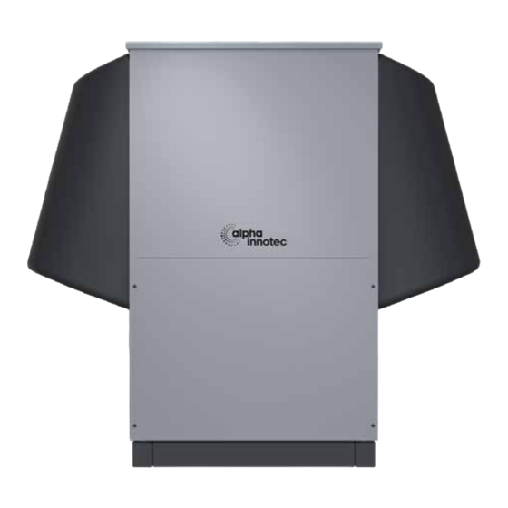
Alpha-InnoTec LWAV+ Series Operating Manual
Air/water heat pumps, outdoor installation
Hide thumbs
Also See for LWAV+ Series
:
Operating manual
(44 pages)
1
Table Of Contents
2
3
4
5
6
7
8
9
10
11
12
13
14
15
16
17
18
19
20
21
22
23
24
25
26
27
28
29
30
31
32
33
34
35
36
37
38
39
40
41
42
43
44
45
46
47
48
49
50
51
52
53
54
55
56
page
of
56
Go
/
56
Contents
Table of Contents
Bookmarks
Table of Contents
Table of Contents
1 About this Operating Manual
Validity
Reference Documents
Symbols and Markings
Contact
2 Safety
Intended Use
Personnel Qualifications
Personal Protective Equipment
Residual Risks
Disposal
Avoid Material Damage
3 Description
As-Delivered Condition
Design
Accessories
Function
4 Operation and Care
Energy and Environmentally Aware Operation
Care
5 Delivery, Storage, Transport and Installation
Scope of Supply
Storage
Unpacking and Transport
Installation
6 Installation of Hydraulic System
7 Electrical Installation
8 Flushing, Filling and Venting
Heating Water Quality
Flushing, Filling and Venting the Heating Circuit
9 Insulation of Hydraulic Connections
10 Setting the Overflow Valve
11 Commissioning
12 Maintenance
Basic Principles
Maintenance after Commissioning
Maintenance as Required
Cleaning and Flushing the Condenser
Annual Maintenance
13 Faults
14 Dismantling and Disposal
Dismantling
Disposal and Recycling
Technical Data / Scope of Supply
Performance Curves
Lwav+ 82R1/3
Lwav+ 122R3
Dimensional Drawings 1
Installation Plans
Minimum Clearances
Connection Set IPWAV Vertical
Surface Foundation
Strip Foundation
Connection Set WDFAV Horizontal
Surface Foundation
Strip Foundation
With Condensate Drain Vertical
Coastal Installation
Condensate Line Connection
External Condensate Line Connection
Internal Condensate Line Connection
Hydraulic Integration
LWAV+ with Hydraulic Station
LWAV+ with Buffer Tank in Series and Hydraulic Module
LWAV+ with Separation Buffer Tank
Keys Hydraulic Integration
Circuit Diagrams
Lwav+ 82R1/3
Lwav+ 122R3
Advertisement
Quick Links
Download this manual
OPERATING MANUAL
LWAV+ SERIES
83024000gUK
UK
Air/Water heat pumps
Outdoor installation
www.alpha-innotec.com
Table of
Contents
Previous
Page
Next
Page
1
2
3
4
5
Advertisement
Table of Contents
Need help?
Do you have a question about the LWAV+ Series and is the answer not in the manual?
Ask a question
Questions and answers
Related Manuals for Alpha-InnoTec LWAV+ Series
Heat Pump alpha innotec LWAV+ 82R1/3 Operating Manual
Air/water heat pumps (44 pages)
Heat Pump Alpha-InnoTec LWAV Series Operating Manual
Air/water (44 pages)
Heat Pump Alpha-InnoTec LWAV Series Operating Manual
Air/water heat pumps (44 pages)
Heat Pump Alpha InnoTec LW Operating Manual
Air/water heat pump outdoor installation (48 pages)
Heat Pump alpha innotec LWAV alira Operating Manual
Air/water heat pumps (41 pages)
Heat Pump Alpha-InnoTec LW A Series Operating Manual
Air/water heat pumps outdoor installation (72 pages)
Heat Pump alpha innotec LW A Series Operating Manual
Air/water heat pumps (24 pages)
Heat Pump Alpha-InnoTec LWCV Series Operating Manual
Air/water heat pumps (52 pages)
Heat Pump Alpha-InnoTec LWCV Series Operating Manual
Air/water heat pumps indoor installation (52 pages)
Heat Pump Alpha-InnoTec LWA Series Operating Manual
Air/water heat pumps outdoor installation (32 pages)
Heat Pump Alpha-InnoTec LWAV 82 Operating Manual
Air/water heat pumps, outdoor installation (56 pages)
Heat Pump Alpha-InnoTec LWAV 122 Operating Manual
Air/water heat pumps, outdoor installation (56 pages)
Heat Pump Alpha innotec LW 71A Operating Manual
Air/water heat pumps outdoor installation lw a series (76 pages)
Heat Pump alpha innotec LW 100H Operating Manual
Air/water heat pumps (48 pages)
Heat Pump Alpha innotec LW 160H/V Operating Manual
Air/water heat pumps (40 pages)
Heat Pump alpha innotec LWV 82R1/3 Operating Manual
Air/water heat pumps (44 pages)
This manual is also suitable for:
Lwav series
Lwav+ 82r1/3
Lwav+ 122r3
Lwav 82
Lwav 122
Table of Contents
Print
Rename the bookmark
Delete bookmark?
Delete from my manuals?
Login
Sign In
OR
Sign in with Facebook
Sign in with Google
Upload manual
Upload from disk
Upload from URL


Need help?
Do you have a question about the LWAV+ Series and is the answer not in the manual?
Questions and answers