
Related Manuals for Alpha-InnoTec LW Series


Summary of Contents for Alpha-InnoTec LW Series
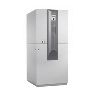
- Page 1 Operati ng manual aIr/water Heat PumPs Inside installation Lw 100 - Lw 190 Lw 150H(L) We reserve the right to modify technical specifications without prior notice. UK830304/190810 © Alpha-InnoTec GmbH...
-
Page 2: Please Read First
Please read first symbols This operating manual provides important information The following symbols are used in the operating manual. on the handling of the unit. It is an integral part of the They have the following meaning: product and must be stored so that it is accessible in the immediate vicinity of the unit. -
Page 3: Table Of Contents
Contents commISSIoNING ..............22 INfoRmATIoN foR opeRAToRS ANd Safety temperature limiter ..........22 qUAlIfIed SpecIAlISTS dISmANTlING .................23 pleASe ReAd fIRST ..............2 TecHNIcAl dATA / Scope of delIveRy SymbolS ..................2 lW 100 - lW 190 ..............24 lW 150H(l) .................26 INTeNded USe ................4 peRfoRmANce cURveS exclUSIoN of lIAbIlITy ............4 Heating capacity/cop / power consumption / ec coNfoRmITy ..............4... -
Page 4: Intended Use
Intended use safety The unit may be used only for the intended purpose. The unit is operationally safe when used for the intended This means: purpose. The construction and design of the unit conform to the state of the art, all relevant dIN/vde •... -
Page 5: Customer Service
warranty / Guarantee CautIon. Install the heat pump only indoors and operate only with outside air as the heat for warranty and guarantee conditions, please refer to source. the air ducts must discharge into the purchase documents. the open air. Do not restrict or block the air ducts. -
Page 6: Functioning Principle Of Heat Pump System
Functioning principle of heat Heat quantity recording pump system In addition to proof of the unit's efficiency, heating legislation also requires heat quantity recording (referred Heat pumps operate on the principle of a refrigerator: to as Wme in this manual). The Wme is mandatory with the same technology, only with the opposite effect. -
Page 7: Care Of The Unit
Care of the unit malfunctions The outer surfaces of the unit can be cleaned with a In the event of a malfunction, you can detect the cause of damp cloth and household cleaning products. the malfunction via the diagnostic program of the heating and heat pump regulator. -
Page 8: Scope Of Delivery
scope of delivery proceed as follows: example of scope of delivery: Inspect delivery for outwardly visible signs of damage. view 1: check to make sure that delivery is complete. Any defects or incorrect deliveries must be claimed immediately. notICe. note the model. Check the air blow-out direction of the unit. -
Page 9: Installation And Assembly
Installation and assembly transport to installation loCation To prevent damage during transport, always transport observe the following when performing all work: the unit to final installation location in its original packag- ing, using a lifting truck. notICe. If it is not possible to transport the unit to the final instal- always comply with applicable accident lation location using a lifting truck, you can also transport prevention regulations, statutory regula-... -
Page 10: Installation
installation lifting the unit with pipes Set the unit on a stable, solid and level, preferably The units can be lifted with " and/or 1" pipes (provided sound-insulated surface. make sure that the foundation by customer) that are suitable for the weight of the is designed for the weight of the heat pump. -
Page 11: Mounting The Air Ducts
mounting the air duCts Insert the pipes through the holes in the frame on the switch cabinet side (= operator side)... notICe. note the air blow-out direction of the unit. – units with the abbreviation L in the model designation blow the air out to the left (when viewed from the control side). - Page 12 Install the wall duct in the masonry from the Affix an additional part as illustrated... house exterior. This can either be done during the construction phase (by means of sealing)... notICe. Mount the wall ducts 1 cm above the fin- ished outer facade.
- Page 13 air duCts assembly seCuring the air duCt into the wall duCt proceed as follows: proceed as follows: Remove the parts necessary for the assembly of the pull the roll seal included with delivery over the end air duct(s) from their respective boxes... of the air duct...
- Page 14 seCuring the air duCt on the heat pump sCreen frame assembly proceed as follows: Screw the screen frame to the wall ducts on both the air intake and output sides. clip on the assembly rail and secure it using special screws to the spots on the air duct designated as the air intake side...
-
Page 15: Installation / Connection To Heating Circuit
installation / ConneCtion to heating CirCuit position the wire mesh grille in the assembly frame... CautIon. Connect the unit to the heating circuit according to the hydraulic diagram for the respective model. “Hydraulic connection” instructions. notICe. Check to make sure that the diameters and lengths of the pipes for the heating circuit are sufficiently dimensioned. -
Page 16: Condensate Discharge
Condensate disCharge Install shut-off devices for the hot water outflow (forward flow) and hot water inflow (return flow) The condensation water that accumulated from the air on the heat pump side. must be drained via the pre-mounted hose in the unit for condensate discharge. -
Page 17: Pressure Relief
Pressure relief Circulating pumps equip the heating circuit in accordance with local stand- CautIon. ards and directives with a safety valve and an expansion tank. always note the model. Also install filling and emptying devices, shut-off devices Do not use regulated circulating pumps. and non-return valves in the heating circuit. -
Page 18: Electrical Connections
electrical connections • cut out the rubber sockets on the facing panel... observe the following when performing all work: for positioning of the rubber sockets for insert- ing the wires, see "dimensional drawing" for the Danger! respective model. Danger of fatal injury due to electric shock! •... -
Page 19: Rinsing, Filling And Bleeding The System
Installation of the control If such a connection is desired, lay a category 6 screened network cable with element rJ-45 plug through the unit parallel to the heating and heat pump regulator control cable already present when making the connections, and lead it through the front Danger! panel of the unit. -
Page 20: Installation And Removal Of The Screen
proceed as follows: notICe. a connection to a computer or a network Hang the control element's hooks on the recesses can be installed via the left bushing on the of the front facade (either in the upper or lower bottom of the control element, allowing recesses)... -
Page 21: We Reserve The Right To Modify Technical Specifications Without Prior Notice
Screen at time of delivery: 1 recess for control element 2 logo 3 temporary cover next, on the opposite side, moving upwards. first, insert the screen below, in the provided slots lock the screen's snap-in lugs in place in the slots on the front of the facade... -
Page 22: Commissioning
Commissioning The heat pump system will be commissioned by cus- tomer service personnel authorised by the manu- facturer. A charge is made for commissioning! Danger! the unit may be commissioned only safety temperature limiter with the air ducts and weather grille or rain guard installed and with the covers A safety temperature limiter is built into the electric closed. -
Page 23: Dismantling
Dismantling Danger! Danger of fatal injury due to electric shock! electrical connections may be installed only by qualified electricians. Before opening the unit, disconnect the system from the power supply and secure it from being switched back on! Danger! only qualified heating or cooling system technicians are allowed to remove the unit from the system. -
Page 24: Technical Data / Scope Of Delivery
technical data / scope of delivery Model designation Heat pump type Brine/water ı Air/water ı Water/water • applicable ı — not applicable Installation location Indoors ı Outdoors • applicable ı — not applicable Conformity Performance data Heating capacity/COP at 2 Compressors kW ı... - Page 25 LW 100 LW 120 LW 150 LW 190 — ı • ı — — ı • ı — — ı • ı — — ı • ı — • ı — • ı — • ı — • ı — •...
- Page 26 technical data / scope of delivery Model designation Heat pump type Brine/water ı Air/water ı Water/water • applicable ı — not applicable Installation location Indoors ı Outdoors • applicable ı — not applicable Conformity Performance data Heating capacity/COP at 2 Compressors kW ı...
-
Page 27: Lw 150H(L)
LW 150H(L) — ı • ı — • ı — • — 10,0 ı 3,4 — 10,6 ı 3,0 — 9,1 ı 3,2 — 10,7 ı 3,6 — 8,1 ı 2,8 — 7,7 ı 1,4 20 – 63 (65)*) -20 – 35 3400 700 ı... -
Page 28: Performance Curves
Lw 100 Performance curves Qh (kW) Temp„ (°C) Pe (kW) 35°C 1VD 50°C 1VD Temp„ (°C) Temp„ (°C) ∆p (bar) ∆p” “” (m³/h) 823119 Legende: DE823129L/170408 “” Volumenstrom Heizwasser Temp„ Temperatur Wärmequelle Heizleistung Legend: UK823129L/170408 Leistungsaufnahme “” Volume flow, heating water Coefficient of performance / Leistungszahl ∆p”... - Page 29 Performance curves Lw 120 Qh (kW) Temp„ (°C) Pe (kW) 35°C 1VD 50°C 1VD Temp„ (°C) Temp„ (°C) ∆p (bar) ∆p” “” (m³/h) 823142 Legende: DE823129L/170408 “” Volumenstrom Heizwasser Temp„ Temperatur Wärmequelle Heizleistung Legend: UK823129L/170408 Leistungsaufnahme “” Volume flow, heating water Coefficient of performance / Leistungszahl Temp„...
- Page 30 Lw 150 Performance curves Qh (kW) Temp„ (°C) Pe (kW) 35°C 1 VD 50°C 1 VD 35°C 2 VD 50°C 2 VD Temp„ (°C) Temp„ (°C) ∆p (bar) ∆p” “” (m³/h) 823121-b Legende: DE823129L/170408 “” Volumenstrom Heizwasser Temp„ Temperatur Wärmequelle Heizleistung Legend: UK823129L/170408...
- Page 31 Performance curves Lw 190 Qh (kW) Temp„ (°C) Pe (kW) 35°C 1VD 50°C 1VD 35°C 2VD 50°C 2VD Temp„ (°C) Temp„ (°C) ∆p (bar) ∆p” “” (m³/h) 823122a Legende: DE823129L/170408 “” Volumenstrom Heizwasser Temp„ Temperatur Wärmequelle Heizleistung Legend: UK823129L/170408 Leistungsaufnahme “”...
-
Page 32: Lw 150H(L)
Lw 150H(L) Performance curves Qh (kW) Temp„ (°C) Pe (kW) 35°C 1VD 50°C 1VD 65°C 1VD Temp„ (°C) Temp„ (°C) ∆p (bar) ∆p” “” (m³/h) 823125 Legende: DE823129L/170408 “” Volumenstrom Heizwasser Temp„ Temperatur Wärmequelle Heizleistung Legend: UK823129L/170408 Leistungsaufnahme “” Volume flow, heating water Coefficient of performance / Leistungszahl ∆p”... -
Page 33: Dimensional Drawings
Dimensional drawings Lw 100, Lw 120, Lw 150H 4x M8 1353 1298 1261 4x M8 1298 1261 Legende: D819158a Legend: UK819158a Pos. Bezeichnung Technische Änderungen vorbehalten. All dimensions in mm. Alle Maße in mm. Bedienteil Front view Heizwasser Austritt (Vorlauf) G 1"... - Page 34 Lw 150HL Dimensional drawings 1353 1298 1261 4x M8 4x M8 1298 1261 Legende: D819170a Legend: UK819170a Pos. Bezeichnung Technische Änderungen vorbehalten. All dimensions in mm. Alle Maße in mm. Bedienteil Front view Heizwasser Austritt (Vorlauf) G 1" DIN ISO 228 Vorderansicht Side view from left Seitenasicht von links...
-
Page 35: Installation Plans Lw 100, Lw 120, Lw 150H(L) Installation Plan Version 1
Installation plan version 1 Lw 100, Lw 120, Lw 150H(L) Legend: UK819307-1 All dimensions in mm. Item Designation Dim. With finished wall thickness 240 to 320 2060 With finished wall thickness 320 to 400 1980 With finished wall thickness 240 to 320 With finished wall thickness 320 to 400 Item Designation Version 1... -
Page 36: Installation Plan Version 2
Lw 100, Lw 120, Lw 150H(L) Installation plan version 2 Legend: UK819307-2 All dimensions in mm. Item Designation Dim. With finished wall thickness 240 to 320 2060 With finished wall thickness 320 to 400 1980 With finished wall thickness 240 to 320 With finished wall thickness 320 to 400 Item Designation Version 2... -
Page 37: Installation Plan Version 3
Installation plan version 3 Lw 100, Lw 120, Lw 150H(L) Legend: UK819307-3 All dimensions in mm. Item Designation Dim. With finished wall thickness 240 to 320 With finished wall thickness 320 to 400 Item Designation Version 3 Accessory: wall duct 800x800x420 Top edge of finished floor Accessory: air duct 700x700x450 Finished outer façade... -
Page 38: Installation Plan Version 4
Lw 100, Lw 120, Lw 150H Installation plan version 4 Legend: UK819307-4 All dimensions in mm. Item Designation Dim. With finished wall thickness 240 to 320 With finished wall thickness 320 to 400 Item Designation Version 4 Accessory: wall duct 800x800x420 Top edge of finished floor Accessory: air duct 700x700x450 Finished outer façade... -
Page 39: Installation Plan Version 5
Installation plan version 5 Lw 150HL Legend: UK819307-5 All dimensions in mm. Item Designation Dim. With finished wall thickness 240 to 320 With finished wall thickness 320 to 400 Item Designation Version 5 Accessory: wall duct 800x800x420 Top edge of finished floor Accessory: air duct 700x700x450 Finished outer façade Accessory: air duct 700x700x1000... -
Page 40: Dimensional Drawings
Lw 150 - Lw 190 Dimensional drawings 4x M8 1523 1381 1372 4x M8 1381 1372 Legende: D819175b Pos. Bezeichnung Technische Änderungen vorbehalten. Legend: UK819175b Alle Maße in mm. Bedienteil All dimensions in mm. Vorderansicht Länge ab Gerät 1m Kondensatschlauch Ø i 30 Front view Seitenasicht von links Side view from left... -
Page 41: Installation Plan Version 1
Installation plan version 1 Lw 150 - Lw 190 Legend: UK819308-1 All dimensions in mm. Item Designation Dim. With finished wall thickness 240 to 320 2160 With finished wall thickness 320 to 400 2080 With finished wall thickness 240 to 320 With finished wall thickness 320 to 400 Item Designation Version 1... -
Page 42: Installation Plan Version 2
Lw 150 - Lw 190 Installation plan version 2 Legend: UK819308-2 All dimensions in mm. Item Designation Dim. With finished wall thickness 240 to 320 2160 With finished wall thickness 320 to 400 2080 With finished wall thickness 240 to 320 With finished wall thickness 320 to 400 Item Designation Version 2... -
Page 43: Installation Plan Version 3
Installation plan version 3 Lw 150 - Lw 190 Legend: UK819308-3 All dimensions in mm. Item Designation Dim. With finished wall thickness 240 to 320 With finished wall thickness 320 to 400 Item Designation Version 3 Accessory: wall duct 800x800x420 Top edge of finished floor Accessory: air duct 700x700x450 Finished outer façade... -
Page 44: Installation Plan Version 4
Lw 150 - Lw 190 Installation plan version 4 Legend: UK819308-4 All dimensions in mm. Item Designation Dim. With finished wall thickness 240 to 320 With finished wall thickness 320 to 400 Item Designation Version 4 Accessory: wall duct 800x800x420 Top edge of finished floor Accessory: air duct 700x700x450 Finished outer façade... -
Page 45: Terminal Diagrams
terminal diagram Lw 100 - Lw 190. Lw 150H(L) 3~N/PE/400V/50Hz 3~PE/400V/50Hz 3~N/PE/400V/50Hz 1~N/PE/230V/50Hz B10 A ZW2/SST We reserve the right to modify technical specifications without prior notice. UK830304/190810 © Alpha-InnoTec GmbH... - Page 46 Lw 100, Lw 120 Circuit diagram 1/3 We reserve the right to modify technical specifications without prior notice. UK830304/190810 © Alpha-InnoTec GmbH...
- Page 47 Circuit diagram 2/3 Lw 100, Lw 120 ZUP/ZIP We reserve the right to modify technical specifications without prior notice. UK830304/190810 © Alpha-InnoTec GmbH...
-
Page 48: Circuit Diagrams
Lw 100, Lw 120 Circuit diagram 3/3 We reserve the right to modify technical specifications without prior notice. UK830304/190810 © Alpha-InnoTec GmbH... - Page 49 Circuit diagram 1/3 Lw 150, Lw 190 We reserve the right to modify technical specifications without prior notice. UK830304/190810 © Alpha-InnoTec GmbH...
- Page 50 Lw 150, Lw 190 Circuit diagram 2/3 ZUP/ZIP We reserve the right to modify technical specifications without prior notice. UK830304/190810 © Alpha-InnoTec GmbH...
- Page 51 Circuit diagram 3/3 Lw 150, Lw 190 We reserve the right to modify technical specifications without prior notice. UK830304/190810 © Alpha-InnoTec GmbH...
-
Page 52: Lw 150H(L)
Lw 150H(L) Circuit diagram 1/3 We reserve the right to modify technical specifications without prior notice. UK830304/190810 © Alpha-InnoTec GmbH... - Page 53 Circuit diagram 2/3 Lw 150H(L) ZUP/ZIP We reserve the right to modify technical specifications without prior notice. UK830304/190810 © Alpha-InnoTec GmbH...
- Page 54 Lw 150H(L) Circuit diagram 3/3 We reserve the right to modify technical specifications without prior notice. UK830304/190810 © Alpha-InnoTec GmbH...
-
Page 55: Ec Declaration Of Conformity
eC declaration of conformity The undersigned confirms that the following designated device(s) as designed and marketed by us fulfil the standardised ec directives, the ec safety standards and the product-specific ec standards. In the event of modification of the device(s) without our approval, this declaration shall become invalid. designation of the deviCe(s) Heat pump unit model... - Page 56 We reserve the right to modify technical specifications without prior notice. UK830304/190810 © Alpha-InnoTec GmbH...
-
Page 57: General Checklist
General checklist for preparation of the Completion report for heat pump systems The general checklist is intended as an aid for the installation and assembly personnel. It makes no claim to be exhaustive. Nevertheless, all items must be checked carefully for compliance. Heat source air Heating ... -
Page 59: Completion Report For Heat Pump Systems
Completion report for heat pump systems in de: to the Alpha-InnoTec customer service department ..............+49 (0) 9228 9906 199 in AT: to the Alpha-InnoTec customer service department ..............+43 (0) 732 24 42 014 in cH: to the Alpha-InnoTec customer service department ..............+41 (0) 62 748 20 01 In all other countries: to the manufacturer’s local partner: ............................ -
Page 61: Space For Notes
space for notes We reserve the right to modify technical specifications without prior notice. UK830304/190810 © Alpha-InnoTec GmbH... -
Page 62: Customer Service
Customer service addresses in the event of a serviCe Call for a current list and additional partners of the manufacturer, please visit www.alpha.innotec.com. Suisse romande Alpha-InnoTec GmbH calmotherm SA Industriestrasse 3 ch. de la venoge 7 95359 Kasendorf 1025 St. Sulpice Tel.: +49 (0) 9228 99 06 190 Tel.:... - Page 63 Geosolar europe ltd. Alpha-InnoTec Norge AS Krisztina körút 27 langgaten 59 1122 budapest 4306 Sandnes Tel.: +36 (0) 1 356 20 46 Tel.: +47 (0) 51 6605 95 fax: +36 (0) 1 214 28 68 fax: +47 (0) 51 6605 94 info@geosolar.hu info@alpha-innotec.no www.geosolar.hu...
Need help?
Do you have a question about the LW Series and is the answer not in the manual?
Questions and answers