
Related Manuals for Riello Burners RL 70/2


Summary of Contents for Riello Burners RL 70/2
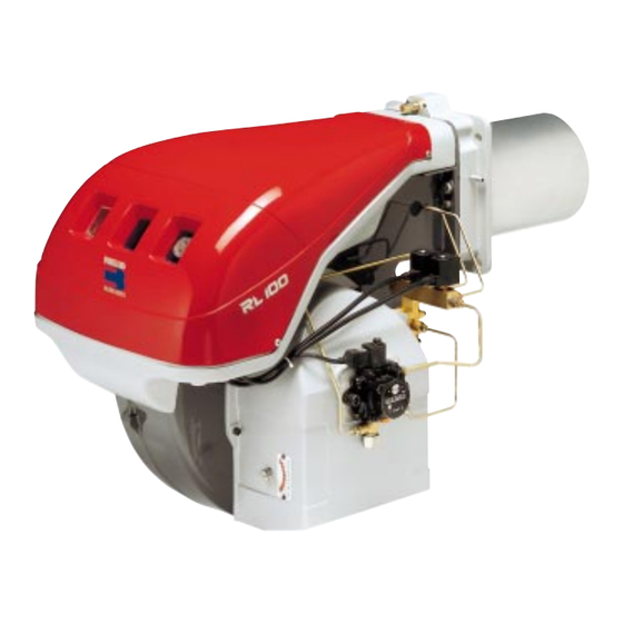
- Page 1 Installation, use and maintenance instructions Light Oil Burners RL 70/2 - 100/2 - 130/2 Low - High Operation C6505052...
-
Page 2: Table Of Contents
CONTENTS WARNING Do not store flammable or hazardous materials in the vicinity TECHNICAL DATA ......page 3 Burner models . -
Page 3: Technical Data
TECHNICAL DATA MODEL RL 70 RL 100 RL 130 Output High fire MBtu/hr 1792 - 3136 2688 - 4480 3584 - 5824 Delivery 12.8 - 22.4 19.2 - 32 25.6 - 41.6 Low fire MBtu/hr 966 - 1792 1344 - 2688 1834 - 3584 6.9 - 12.8 9.6 - 19.2... -
Page 4: Burner Description
BURNER DESCRIPTION (A) 1 Ignition electrodes 2 Combustion head 3 Screw for combustion head adjustment 4 Screw for fixing fan to flange 5 Slide bars for opening the burner and inspecting the combustion head 6 Safety solenoid valve 7 Pump 8 Air inlet to fan 9 Air damper 10 Hydraulic cylinder for regulation of the air damper... -
Page 5: Firing Rate
FIRING RATE (A) The RL 70 - 100 - 130 Model burners can work in two ways: Low and High fire. LOW FIRE DELIVERY must be selected within area A of the adjacent diagrams. HIGH FIRE DELIVERY must be selected within area B (and C for model RL 130). -
Page 6: Installation
INSTALLATION inch BOILER PLATE (A) Drill the combustion chamber mounting plate as RL 70 “ “ - 12 “ 1 / 2 9 / 32 27 / 32 13 / 16 shown in (A). The position of the threaded holes can RL 100 “... -
Page 7: Nozzle Assembly
The two nozzles usually have equal deliveries, but the low fire nozzle may have the following specifications if required: • a delivery less than 50% of the total delivery when- ever the back-pressure peak must be reduced at the moment of firing: the burner allows good combustion values also with a ratio 40 - 100 % between low and high fire;... -
Page 8: Fuel Supply
HYDRAULIC SYSTEM FUEL SUPPLY Double-pipe circuit (A) The burner is equipped with a self-priming pump which is capable of feeding itself within the limits listed in the table at the left. The tank higer than the burner A The distance "P" must not exceed 32 ft in order to avoid subjecting the pump's seal to excessive strain;... -
Page 9: Pump
PUMP (A) 1 - Suction 1/4” NPT RL 70 - 100 - 130: SUNTEC AJ6 2 - Return 1/4” NPT 3 - Pressure gauge attachment G 1/8 4 - Vacuum gauge attachment G 1/8 5 - Pressure adjustment screw 6 - Screw for by-pass A - Min. -
Page 10: Burner Calibration
BURNER CALIBRATION FIRING Set switch 1)(C) to "ON". During the first firing, during the switch over from low to the high fire, there is a momentary lowering of the fuel pressure caused by the filling of the high fire noz- zle tubing. -
Page 11: Final Check
FINAL CHECKS • Obscure the photocell and switch on the control devic- es: the burner should start and then lock-out about 5 s after opening of the low fire nozzle operation valve. • Illuminate the photocell and switch on the control cir- cuit: the burner should go into lock-out . -
Page 12: Burner Operation
BURNER OPERATION BURNER STARTING (A) Operating control closes. The motor starts and the ignition transformer is con- nected. The pump 3) sucks the fuel from the tank through the piping 1) and the filter 2) and pumps it under pressure to delivery. -
Page 13: Factory Wiring Diagram - Burner Mounted Lal Control
Factory Wiring Diagram RL70 - 130 three phase with burner mounted Siemens LAL control D2428 Continuous fan operation Change the wire connection from terminal 7 to terminal 1, remove the jumper between terminals 12-13 and the wire from terminal 13 of control box. D2872 LAYOUT (A) - Photocell... -
Page 14: Field Wiring Diagram- Burner Mounted Lal Control
Field Wiring Diagram RL 70 - 130 three phase burner with burner mounted LAL flame safeguard RL 70 RL 100 RL 130 208-230 V 460 V 575 V 208-230 V 460 V 575 V 208-230 V 460 V 575 V T 10 T 15 T 10... -
Page 15: Factory Wiring Diagram - Remote Panel
Factory Wiring Diagram RL70 - 130 three phase with remote control panel D2429 LAYOUT (A) Burners RL 70 - 100 - 130 The flame safeguard is in remote panel. See the internal electrical systems of the remote panel in order to have the complete wiring diagram. Key to Layout (A) - Motor contactor - Control box... -
Page 16: Appendix - Burner Firing Rates According To Air Density
APPENDIX - Burner firing rates according to air density CORRECTION FACTOR average barom. above sea level Air temperature pressure °F (°C) “ W.C. mbar 0 (0°C) 41 (5°C) 50 (10°C) 59 (15°C) 68 (20°C) 77 (25°C) 86 (30°C) 104 (40°F) 1013 1,087 1,068... -
Page 17: Siemens Lal Control Sequence Of Operations
SEQUENCE OF OPERATION Siemens LAL control Switching times are given in seconds, in the burner startup sequence. LAL 2.25 optional optional Legend for the times Pre-purge time with air damper open. Safety time. Pre-ignition time, short (“Z” connected terminal “16”). Interval between voltage at terminals “18”... -
Page 18: Siemens Lal Control Troubleshooting Guide
BURNER FAULTS Control program under fault conditions and lock-out indication Whenever a fault occurs, the sequence switch stops and with it the lock-out indicator. The symbol above the reading mark of the indicator gives the type of fault: No start One of the contacts has not closed The contact of the limit thermostat or any other switching devices in the control loop of terminal 4 to terminal 5 are... -
Page 19: Start Up Report
BURNER START UP REPORT Model number: Serial number: Project name: Start-up date: Installing contractor: Phone number: GAS OPERATION Gas Supply Pressure: : Low Fire High Fire Main Power Supply: : Low Fire High Fire Control Power Supply: CO: Low Fire High Fire Burner Firing Rate: : Low Fire... - Page 20 Represented By: Power Equipment Company 2011 Williamsburg Road Richmond, VA 23231 Ph: 804-236-3800 Fx: 804-236-3882 www.peconet.com...
Need help?
Do you have a question about the RL 70/2 and is the answer not in the manual?
Questions and answers