Table of Contents
Advertisement
Quick Links
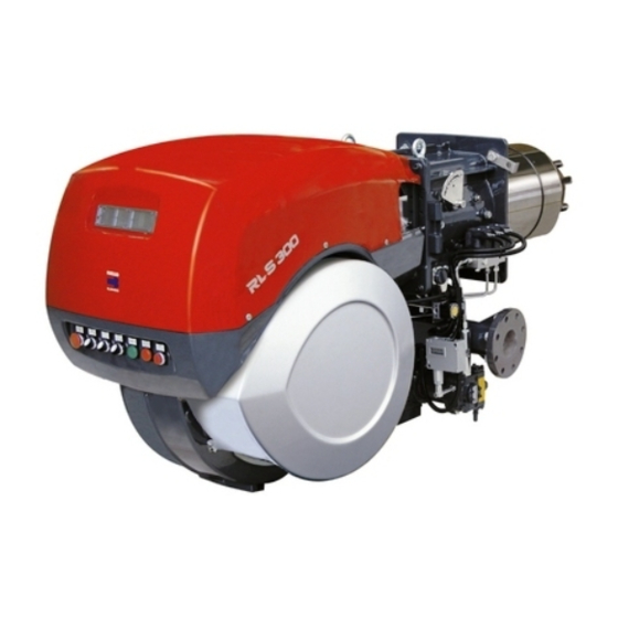
LOW NOx DUAL FUEL BURNERS
RLS/E-EV MX SERIES
RLS/E-EV MX series burners are characterised by a modular monoblock structure that
means all necessary components can be combined in a single unit thus making installation
easier, faster and, above all, more flexible.
The series covers a firing range from 600 to 4300 kW, and they have been designed for
use in hot water boilers, overheated water boilers as well as steamboilers. Operation can
be "two stage progressive" or alternative "modulating" with the installation of a PID logic
regulator. The burner can, therefore, supply with precision the demanded power, guaranteeing
an high efficiency system level and the stability setting, obtaining fuel consumption and
operating costs reduction.
The innovative combustion head, adjustment system ensures perfect movement during
modulation as well as reducing noise and pollutants.
600/1250 ÷ 3550 kW
RLS 300/E MX
800/1800 ÷ 4300 kW
RLS 400/E MX
RLS 300/EV MX 600/1250 ÷ 3550 kW
RLS 400/EV MX 800/1800 ÷ 4300 kW
TS0070UK01
Advertisement
Table of Contents

Related Manuals for Riello Burners RLS 300/E MX


Summary of Contents for Riello Burners RLS 300/E MX
- Page 1 LOW NOx DUAL FUEL BURNERS 600/1250 ÷ 3550 kW RLS/E-EV MX SERIES RLS 300/E MX 800/1800 ÷ 4300 kW RLS 400/E MX RLS 300/EV MX 600/1250 ÷ 3550 kW RLS 400/EV MX 800/1800 ÷ 4300 kW RLS/E-EV MX series burners are characterised by a modular monoblock structure that means all necessary components can be combined in a single unit thus making installation easier, faster and, above all, more flexible.
-
Page 2: Technical Data
TECHNICAL DATA Model RLS 300/E MX RLS 400/E MX RLS 300/EV MX RLS 400/EV MX Burner operation mode two stages progressive/modulating 1 ÷ 4 Modulation ratio at max. output type SQM 48 (OIL and GAS) Servomotor run time 600/1250÷3550 800/1800÷4300 600/1250÷3550... -
Page 3: Firing Rates
FIRING RATES RLS 400/E-EV MX RLS 300/E-EV MX 1000 1500 2000 2500 3000 3500 4000 4500 Mcal/h 1000 1500 2000 2500 3000 3500 4000 4500 5000 Useful working field for choosing the burner Modulation range Test conditions conforming to EN 676: Temperature: 20°C Pressure: 1000 mbar Altitude: 100 m a.s.l. -
Page 4: Fuel Supply
FUEL SUPPLY GAS TRAIN The burners are fitted with a butterfly valve to regulate the fuel, controlled by the main management module of burner through a high precision servomotor. Fuel can be supplied either from the right or left sides, on the basis of the application requirements. - Page 5 Example of gas train “COMPOSED” type without seal control Ø o Ø i Example of gas train “MULTIBLOC” type Ø o without seal control Ø i Gas trains are approved by standard EN 676 together with the burner. The overall dimensions of the gas train depends on how they are constructed. The following table shows the maximum dimensions of the gas trains that can be fitted to RLS 300-400/E-EV MX burners, intake and outlet diameters.
-
Page 6: Pressure Drop Diagram
PRESSURE DROP DIAGRAM The diagrams indicate the minimum pressure drop of the burners with the various gas trains that can be matched with them; at the value of these pressure drop add the combustion chamber pressure. The value thus calculated represents the minimum required input pressure to the gas train. NATURAL GAS RLS 300/E-EV MX Δ... - Page 7 SELECTING THE FUEL SUPPLY LINES The following diagram enables pressure drop in a pre-existing gas line to be calculated and to select the correct gas train. The diagram can also be used to select a new gas line when fuel output and pipe length are known. The pipe diameter is selected on the basis of the desired pressure drop.
-
Page 8: Hydraulic Circuit
HYDRAULIC CIRCUIT The hydraulic circuit of the RLS/E-EV MX series of burners is characterised by a fuel pump with an independent motor. The burners are fitted with two valves (a safety valve and an operation valve) and an oil filter along the oil line from the pump to the nozzle. - Page 9 SELECTING THE FUEL SUPPLY LINES The fuel feed must be completed with the safety devices required by the local norms. The table shows the choice of piping diameter, depending on the difference in height between the burner and the tank and their distance. MAXIMUM EQUIVALENT LENGTH FOR THE PIPING L[m] Model RLS/E-EV MX...
-
Page 10: Combustion Head
VENTILATION The ventilation unit comes with a sound proofing radial regulating system. All the burners in the RLS/E-EV MX series are fitted with fans with reverse curve blades, which give excellent performance and are fitted in line with the combustion head. The air flow and sound-deadening materials used in the construction are designed to reduce sound emissions to the minimum and guarantee high levels of performance in terms of output and... - Page 11 ADJUSTMENT BURNER OPERATION MODE Each RLS/E-EV MX series burner is equipped with an electronic microprocessor management panel, which controls the air damper servomotor as well the fuel servomotors. Hysteresis is prevented by the precise control of the two servomotors and the software link by can - bus. The high precision regulation is due to the absence of mechanical clearance normally found in mechanical regulation cams on traditional modulating burners.
- Page 12 Fan speed control (on demand) The inverter device fitted to the RLS/EV series burner acts on the electrical supply frequency of the fan motor to adjust the air flow through the motor speed variation. The main advantages of speed control: - lower sound emissions - electric power saving.
-
Page 13: Start Up Cycle
Electronic Cam Platform Features: Multifuel Burners LMV51-52 Intermittent Burner Control Operation Valves Seal Control Electronic Cam O2 Regulation Speed Regulation IONISATION / QRI Optional Regulator Continuos Operation 5 IP54 servomotors Fuel meter Output/Efficiency digital signal CAN-Bus AZL display and CAN-Bus operating unit Interface Stepper actuators 3 / 20 / 35 Nm Sensor... -
Page 14: Wiring Diagrams
WIRING DIAGRAMS Electrical connections must be made by qualified and skilled personnel, according to the local norms. Example of the terminal board for electrical connections THREE PHASE SUPPLY TO THE POWER CIRCUIT AND GAS TRAINS CONNECTIONS RLS 300-400/E-EV MX Gas valve + PVP leak detection L1 L2 L3 N -PGMin -PGVP... -
Page 15: Input Connections
INPUT CONNECTIONS FOR RLS 300-400/E MX Power regulation with 3-position contact I Stage II Stage NC NO P ϑ Two stage progressive position FOR RLS 300-400/EV MX Possibility of probe input -BT5 ϑ POWER OUTPUT REFERANCE SUPPLY GROUND Pt /LG Ni 1000 TEMPERATURE /PRESSURE INPUT -BT3 ϑ... -
Page 16: Output Connections
FOR RLS 300-400/EV MX Possibility of setpoint input and setpoint shift Possibility of external modulation -BV1 -BV2 OUTPUT REFERANCE OUTPUT REFERANCE GROUND GROUND 0...10V 2...10V SET POINT EXTERNAL MODULATION -BA1 -BA3 OUTPUT REFERANCE OUTPUT REFERANCE GROUND GROUND 4...20 mA 4...20 mA SET POINT EXTERNAL MODULATION OUTPUT CONNECTIONS... -
Page 17: Optional Connection
OPTIONAL CONNECTION FOR RLS 300-400/E MX WITH RWF40 POWER CONTROL KIT Possibility of probe input -BT1 -BT2 -BT3 ϑ ϑ 0 - 20mA 4 - 20mA DC 0 - 1V 0 - 10V DC Resistance Thermometer in Resistance Thermometer in Thermocouple Current probe output Voltage probe output... - Page 18 - DC voltage input 0...1 V, 0...10 V for modifying the remote setpoint The following table shows the supply lead sections and the type of fuse to be used. Model RLS 300/E MX RLS 400/E MX RLS 300/EV MX RLS 400/EV MX...
- Page 19 EMISSIONS NO x EMISSIONS RLS 300/E-EV MX RLS 400/E-EV MX NOISE EMISSIONS The emission data has been measured in the various models at maximum output, according to EN 676 and EN 267 standard. RLS 300/E-EV MX RLS 400/E-EV MX The RLS/E-EV MX series combustion head reduce polluting emissions thanks to their special design which optimises the air fuel mix.
-
Page 20: Overall Dimensions (Mm)
OVERALL DIMENSIONS (mm) BURNER RLS 300-400/E-EV MX Model RLS 300/E-EV MX 1325 DN80 1055 1175 RLS 400/E-EV MX 1325 DN80 1055 1175 BURNER - BOILER MOUNTING FLANGE Model Ø 45° RLS 300/E-EV MX RLS 400/E-EV MX 45° Ø PACKAGING Model 1960 RLS 300/E-EV MX RLS 400/E-EV MX... -
Page 21: Installation Description
INSTALLATION DESCRIPTION Installation, start up and maintenance must be carried out by qualified and skilled personnel. All operation must be performed in accordance with the technical handbook supplied with the burner. After drilling the boilerplate, using the supplied gasket as template, prepare a suitable lifting system and, after hooking onto the rings, fix burner to boiler. -
Page 22: Burner Accessories
BURNER ACCESSORIES Nozzles The nozzles must be ordered separately. The following table shows the features and codes on the basis of the maximum required fuel output. Nozzles type B5 SA 60° Burner Rated delivery (kg/h) Nozzle code 3009363 RLS 300-400/E MX 3009364 RLS 300-400/E MX 3009365... - Page 23 Display and Operating Unit (AZL) This tool is needed for combustion system commissioning and monitoring. The AZL is included in RLS/EV models. Display and Operating Unit (AZL) Burner Code 3010355 RLS 300-400/E MX Oxygen Control kit (QGO The QGO is an oxygen analizer with relevant probe which controls and supervises the residual oxygen content in exhaust gases.
-
Page 24: Gas Train Accessories
LPG kit For burning LPG gas, a special kit is available to be fitted to the combustion head of the burner. LPG kit Burner Code in progress RLS 300-400/E-EV MX GAS TRAIN ACCESSORIES Adapters Below are given the adapters than can be fitted on the various burners: Adapters Burner Dimensions... -
Page 25: Specification
3/220/60Hz - 3N/380V/60Hz Auxiliary voltage : 230/50-60 230V/50-60Hz 110/50-60 110V/50-60Hz 3/400/50 230/50-60 BASIC DESIGNATION EXTENDED DESIGNATION AVAILABLE BURNER MODELS RLS 300/E MX FS1/FS2 3/400/50 230/50-60 RLS 400/E MX FS1/FS2 3/400/50 230/50-60 RLS/EV models and other versions are available on specific request. -
Page 26: Product Specification
PRODUCT SPECIFICATION Burner Monoblock forced draught gas burner with modulating operation, fully automatic, made up of: - Fan with reverse curve blades high performance with low sound emissions - Air suction circuit lined with sound-proofing material - Air damper for air setting controlled by a high precision servomotor - Air pressure switch - Fan starting motor at 2800 rpm, three-phase 230/400 - 400/690 V with neutral, 50Hz - Separate light oil pump... - Page 27 Standard equipment: - 1 flange gasket - 4 screws for fixing the flange - 1 thermal screen - 4 screws for fixing the burner flange to the boiler - 2 flexible pipes for connection to the oil supply network - 2 nipples for connection to the pump with gaskets - Seal control - Seal control pressure switch (for installation on gas train) - Instruction handbook for installation, use and maintenance...
- Page 28 RIELLO - Via Ing. Pilade Riello, 5 - 37045 Legnago (VR) Italy S.p.A. Tel. ++39.0442630111 - Fax ++39.044221980 ISO 9001 Cert. n. 0061 Internet: http://www.rielloburners.com - E-mail: info@rielloburners.com Since the Company is constantly engaged in the production improvement, the aesthetic and dimensional features, the technical data, the equipment and the accessories can be changed.
Need help?
Do you have a question about the RLS 300/E MX and is the answer not in the manual?
Questions and answers