
Subscribe to Our Youtube Channel
Related Manuals for Riello Burners RLS 70/E


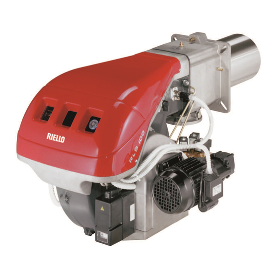
Summary of Contents for Riello Burners RLS 70/E
- Page 1 Installation, use and maintenance instructions Dual Fuel Gas / Light Oil Burners Electronic cam version 11 / 15 / 2002 Preliminary copy RLS 70 - 100 - 130 /E Modulating Gas / Low - High Oil Operation C65050xx - 2915922 (0)
-
Page 2: Table Of Contents
CONTENTS WARNING FUEL OIL / GAS Technical data ........page 3 If you smell gas: Burner models . -
Page 3: Technical Data
L = Standard length L1 = Length obtainable with the kit Code 3010267 L = 9 ” L1 = 15 ” • RLS 70/E 27 / 32 5 / 32 Code 3010268 L = 9 27 / 32 ” L1 = 15 5 / 32 ”... -
Page 4: Burner Description
(B). • The weight of the burner complete with packaging is indicated in Table (B). inch MAX. DIMENSIONS (C) - Approximate measure- RLS 70/E 50“ 25 / 32 “ 3 / 4 “ ments RLS 100/E 50“... -
Page 5: Firing Rates
6. MINIMUM OUTPUT must not be lower than the mini- mum limit shown in the diagram: RLS 70/E = 854 MBtu/hr = 6.1 GPH RLS 100/E = 1330 MBtu/hr = 9.5 GPH RLS 130/E = 1750 MBtu/hr = 12.5 GPH... -
Page 6: Installation
The range of lengths available, L (inch), is as follows: Blast tube 10): RLS 70/E RLS 100/E RLS 130/E • short 27 / 32 “... -
Page 7: Nozzle Assembly
NOZZLE ASSEMBLY Remove screw 1)(E) and extract the nozzle assembly 2)(E) (see page 6). Install both nozzles 1)(A), after hav- ing removed the plastic plugs 2)(A), fitting the wrench through the central hole in the flame stability disk or loosen screws 1)(B), remove disk 2)(B) and replace the nozzles using the wrench 3)(B). -
Page 8: Pump
PUMP (A) PUMP 1 - Suction 1/4” NPT SUNTEC AJ6 CC 2 - Return 1/4” NPT 3 - Pressure gauge attachment G 1/8” 4 - Vacuum gauge attachment G 1/8” 5 - Pressure regulator A - Min. delivery rate at 174 PSI pressure B - Delivery pressure range C - Max. -
Page 9: Fuel Supply
FUEL SUPPLY (A) The burner is equipped with a self-priming pump which is capable of feeding itself within the limits listed in the table at the left. The tank higher than the burner A The distance "P" must not exceed 33 ft in order to avoid subjecting the pump's seal to excessive strain;... -
Page 10: Gas Pressure
GAS PRESSURE ∆p (“ WC) RLS 70/E The adjacent tables show minimum pressure losses along the gas supply line depending on the maximum MBtu/hr burner output. 1750 2.17 0.08 Column 1 1950 2.20 0.08 Pressure loss at combustion head. 2140 2.24... -
Page 11: Gas Line
GAS LINE • The main gas train must be connected to the gas attachment 1)(A), using flange 2), gasket 3) and screws 4) supplied with the burner. • The main gas train can enter the burner from the right or left side, see fig. (A). •... -
Page 12: Adjustment Before Firing
ADJUSTMENTS BEFORE FIRST FIRING LOW GAS PRESSURE SWITCH HIGH GAS PRESSURE SWITCH AIR PRESSURE SWITCH Adjustment of the combustion head has been illustrated on page 7. In addition, the following adjustments must also be made: - Open manual valves up-stream from the gas train. - Adjust the low gas pressure switch to the start of the scale (A). - Page 13 AIR PRESSURE SWITCH (A) AIR PRESSURE SWITCH Adjust the air pressure switch after having performed all other burner adjustments with the air pressure switch set to the start of the scale (A). With the burner operating at min. output, increase adjust- ment pressure by slowly turning the relative dial clock- wise until the burner locks out.
-
Page 14: Maintenance
MAINTENANCE FLAME INSPECTION WINDOW Combustion The optimum calibration of the burner requires an analy- sis of the flue gases. Significant differences with respect to the previous measurements indicate the points where more care should be exercised during maintenance. Gas leaks Make sure that there are no gas leaks on the pipework between the gas meter and the burner. -
Page 15: Oil Hydraulic System Layout
OIL HYDRAULIC SYSTEM LAYOUT (A) 1 Pump suction 2 Filter 3 Pump 4 Pressure regulator 5 Return pipe 6 By-pass screw 7 Pump return 8 Safety solenoid 9 Low fire valve 10 High fire valve 11 Filter M Pressure gauge P low oil pressure switch V Vacuum gauge OIL PRESSURE SWITCH... -
Page 16: Factory Wiring Diagram
Factory Wiring Diagram RLS 70 - 100 - 130/E Layout of electric panel board CONTENTS References layout Functional diagram Functional diagram Functional diagram Key to layouts NOTES QRI detector • The setting of the thermal overload must be according to the total Fan motor thermal overload burner amperage draw. -
Page 20: Appendix - Burner Firing Rates According To Air Density
APPENDIX - Burner firing rates according to air density CORRECTION FACTOR average barom. above sea level Air temperature pressure °F (°C) “ W.C. mbar 0 (0°C) 41 (5°C) 50 (10°C) 59 (15°C) 68 (20°C) 77 (25°C) 86 (30°C) 104 (40°F) 1013 1,087 1,068... -
Page 21: Start Up Report
BURNER START UP REPORT Model number: Serial number: Project name: Start-up date: Installing contractor: Phone number: GAS OPERATION Gas Supply Pressure: : Low Fire High Fire Main Power Supply: : Low Fire High Fire Control Power Supply: CO: Low Fire High Fire Burner Firing Rate: : Low Fire... - Page 24 RIELLO S.p.A. Via degli Alpini 1 I - 37045 Legnago (VR) Tel.: +39.0442.630111 Fax: +39.0442.630375 http:// www.rielloburners.com RIELLO BURNERS NORTH AMERICA 1-800-4-RIELLO 35 Pond Park Road 2165 Meadowpine Blvd. Hingham, Massachusetts, 1-800-474-3556 Mississauga, Ontario, U.S.A. 02043 Canada L5N 6H6 http://www.riello-burners.com...
Need help?
Do you have a question about the RLS 70/E and is the answer not in the manual?
Questions and answers