Table of Contents
Advertisement
Quick Links
Product Information
Original Instructions
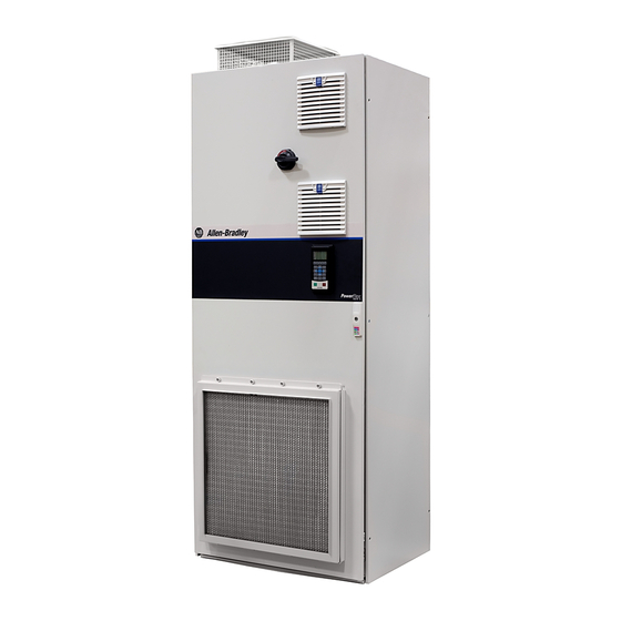
PowerFlex 750-Series Products with TotalFORCE Control
Catalog Numbers 20G, 20J
ATTENTION: Read this document and the documents listed in the Additional Resources section about installation, configuration and operation of this equipment before you install, configure, operate or maintain this
product. Users are required to familiarize themselves with installation and wiring instructions in addition to requirements of all applicable codes, laws, and standards.
Activities including installation, adjustments, putting into service, use, assembly, disassembly, and maintenance are required to be carried out by suitably trained personnel in accordance with applicable code of
practice. If this equipment is used in a manner not specified by the manufacturer, the protection provided by the equipment may be impaired.
ATENCIÓN: Antes de instalar, configurar, poner en funcionamiento o realizar el mantenimiento de este producto, lea este documento y los documentos listados en la sección Recursos adicionales acerca de la
instalación, configuración y operación de este equipo. Los usuarios deben familiarizarse con las instrucciones de instalación y cableado y con los requisitos de todos los códigos, leyes y estándares vigentes.
El personal debidamente capacitado debe realizar las actividades relacionadas a la instalación, ajustes, puesta en servicio, uso, ensamblaje, desensamblaje y mantenimiento de conformidad con el código de práctica
aplicable. Si este equipo se usa de una manera no especificada por el fabricante, la protección provista por el equipo puede resultar afectada.
ATENÇÃO: Leia este e os demais documentos sobre instalação, configuração e operação do equipamento que estão na seção Recursos adicionais antes de instalar, configurar, operar ou manter este produto. Os
usuários devem se familiarizar com as instruções de instalação e fiação além das especificações para todos os códigos, leis e normas aplicáveis.
É necessário que as atividades, incluindo instalação, ajustes, colocação em serviço, utilização, montagem, desmontagem e manutenção sejam realizadas por pessoal qualificado e especializado, de acordo com o
código de prática aplicável.
Caso este equipamento seja utilizado de maneira não estabelecida pelo fabricante, a proteção fornecida pelo equipamento pode ficar prejudicada.
ВНИМАНИЕ: Перед тем как устанавливать, настраивать, эксплуатировать или обслуживать данное оборудование, прочитайте этот документ и документы,
перечисленные в разделе «Дополнительные ресурсы». В этих документах изложены сведения об установке, настройке и эксплуатации данного оборудования.
Пользователи обязаны ознакомиться с инструкциями по установке и прокладке соединений, а также с требованиями всех применимых норм, законов и
стандартов.
Все действия, включая установку, наладку, ввод в эксплуатацию, использование, сборку, разборку и техническое обслуживание, должны выполняться обученным
персоналом в соответствии с применимыми нормами и правилами.
Если оборудование используется не предусмотренным производителем образом, защита оборудования может быть нарушена.
:
ACHTUNG: Lesen Sie dieses Dokument und die im Abschnitt „Weitere Informationen"aufgeführten Dokumente, die Informationen zu Installation, Konfiguration und Bedienung dieses Produkts enthalten, bevor Sie
dieses Produkt installieren, konfigurieren, bedienen oder warten. Anwender müssen sich neben den Bestimmungen aller anwendbaren Vorschriften, Gesetze und Normen zusätzlich mit den Installations- und
Verdrahtungsanweisungen vertraut machen.
Arbeiten im Rahmen der Installation, Anpassung, Inbetriebnahme, Verwendung, Montage, Demontage oder Instandhaltung dürfen nur durch ausreichend geschulte Mitarbeiter und in Übereinstimmung mit den
anwendbaren Ausführungsvorschriften vorgenommen werden.
Wenn das Gerät in einer Weise verwendet wird, die vom Hersteller nicht vorgesehen ist, kann die Schutzfunktion beeinträchtigt sein.
ATTENTION : Lisez ce document et les documents listés dans la section Ressources complémentaires relatifs à l'installation, la configuration et le fonctionnement de cet équipement avant d'installer, configurer,
utiliser ou entretenir ce produit. Les utilisateurs doivent se familiariser avec les instructions d'installation et de câblage en plus des exigences relatives aux codes, lois et normes en vigueur.
Les activités relatives à l'installation, le réglage, la mise en service, l'utilisation, l'assemblage, le démontage et l'entretien doivent être réalisées par des personnes formées selon le code de pratique en vigueur.
Si cet équipement est utilisé d'une façon qui n'a pas été définie par le fabricant, la protection fournie par l'équipement peut être compromise.
:
,
,
,
,
ATTENZIONE Prima di installare, configurare ed utilizzare il prodotto, o effettuare interventi di manutenzione su di esso, leggere il presente documento ed i documenti elencati nella sezione "Altre risorse", riguardanti
l'installazione, la configurazione ed il funzionamento dell'apparecchiatura. Gli utenti devono leggere e comprendere le istruzioni di installazione e cablaggio, oltre ai requisiti previsti dalle leggi, codici e standard
applicabili.
Le attività come installazione, regolazioni, utilizzo, assemblaggio, disassemblaggio e manutenzione devono essere svolte da personale adeguatamente addestrato, nel rispetto delle procedure previste.
Qualora l'apparecchio venga utilizzato con modalità diverse da quanto previsto dal produttore, la sua funzione di protezione potrebbe venire compromessa.
DİKKAT: Bu ürünün kurulumu, yapılandırılması, işletilmesi veya bakımı öncesinde bu dokümanı ve bu ekipmanın kurulumu, yapılandırılması ve işletimi ile ilgili İlave Kaynaklar bölümünde yer listelenmiş dokümanları
okuyun. Kullanıcılar yürürlükteki tüm yönetmelikler, yasalar ve standartların gereksinimlerine ek olarak kurulum ve kablolama talimatlarını da öğrenmek zorundadır.
Kurulum, ayarlama, hizmete alma, kullanma, parçaları birleştirme, parçaları sökme ve bakım gibi aktiviteler sadece uygun eğitimleri almış kişiler tarafından yürürlükteki uygulama yönetmeliklerine uygun şekilde
yapılabilir.
Bu ekipman üretici tarafından belirlenmiş amacın dışında kullanılırsa, ekipman tarafından sağlanan koruma bozulabilir.
POZOR: Než začnete instalovat, konfigurovat či provozovat tento výrobek nebo provádět jeho údržbu, přečtěte si tento dokument a dokumenty uvedené v části Dodatečné zdroje ohledně instalace, konfigurace
a provozu tohoto zařízení. Uživatelé se musejí vedle požadavků všech relevantních vyhlášek, zákonů a norem nutně seznámit také s pokyny pro instalaci a elektrické zapojení.
Činnosti zahrnující instalaci, nastavení, uvedení do provozu, užívání, montáž, demontáž a údržbu musí vykonávat vhodně proškolený personál v souladu s příslušnými prováděcími předpisy.
Pokud se toto zařízení používá způsobem neodpovídajícím specifikaci výrobce, může být narušena ochrana, kterou toto zařízení poskytuje.
UWAGA: Przed instalacją, konfiguracją, użytkowaniem lub konserwacją tego produktu należy przeczytać niniejszy dokument oraz wszystkie dokumenty wymienione w sekcji Dodatkowe źródła omawiające instalację,
konfigurację i procedury użytkowania tego urządzenia. Użytkownicy mają obowiązek zapoznać się z instrukcjami dotyczącymi instalacji oraz oprzewodowania, jak również z obowiązującymi kodeksami, prawem i
normami.
Działania obejmujące instalację, regulację, przekazanie do użytkowania, użytkowanie, montaż, demontaż oraz konserwację muszą być wykonywane przez odpowiednio przeszkolony personel zgodnie z
obowiązującym kodeksem postępowania.
Jeśli urządzenie jest użytkowane w sposób inny niż określony przez producenta, zabezpieczenie zapewniane przez urządzenie może zostać ograniczone.
OBS! Läs detta dokument samt dokumentet, som står listat i avsnittet Övriga resurser, om installation, konfigurering och drift av denna utrustning innan du installerar, konfigurerar eller börjar använda eller utföra
underhållsarbete på produkten. Användare måste bekanta sig med instruktioner för installation och kabeldragning, förutom krav enligt gällande koder, lagar och standarder.
Åtgärder som installation, justering, service, användning, montering, demontering och underhållsarbete måste utföras av personal med lämplig utbildning enligt lämpligt bruk.
Om denna utrustning används på ett sätt som inte anges av tillverkaren kan det hända att utrustningens skyddsanordningar försätts ur funktion.
LET OP: Lees dit document en de documenten die genoemd worden in de paragraaf Aanvullende informatie over de installatie, configuratie en bediening van deze apparatuur voordat u dit product installeert,
configureert, bediend of onderhoudt. Gebruikers moeten zich vertrouwd maken met de installatie en de bedradingsinstructies, naast de vereisten van alle toepasselijke regels, wetten en normen.
Activiteiten zoals het installeren, afstellen, in gebruik stellen, gebruiken, monteren, demonteren en het uitvoeren van onderhoud mogen uitsluitend worden uitgevoerd door hiervoor opgeleid personeel en in
overeenstemming met de geldende praktijkregels.
Indien de apparatuur wordt gebruikt op een wijze die niet is gespecificeerd door de fabrikant, dan bestaat het gevaar dat de beveiliging van de apparatuur niet goed werkt.
,
,
,
,
,
.
.
.
.
,
Advertisement
Table of Contents

Subscribe to Our Youtube Channel
Related Manuals for Rockwell Automation Allen-Bradley PowerFlex 750 TotalFORCE Control Series


Summary of Contents for Rockwell Automation Allen-Bradley PowerFlex 750 TotalFORCE Control Series
- Page 1 Product Information Original Instructions PowerFlex 750-Series Products with TotalFORCE Control Catalog Numbers 20G, 20J ATTENTION: Read this document and the documents listed in the Additional Resources section about installation, configuration and operation of this equipment before you install, configure, operate or maintain this product.
-
Page 2: Additional Resources
PowerFlex 750-Series Products with TotalFORCE Control Product Information Additional Resources These documents contain additional information concerning related products from Rockwell Automation. Resource Description Provides the basic steps to install PowerFlex 755TL drives, PowerFlex 755TR drives, and PowerFlex PowerFlex® 750-Series Products with TotalFORCE® Control Installation Instructions, publication 750-IN100 755TM bus supplies. - Page 3 (8 in.) 254 mm Airflow through the cabinet must not be impeded. (10 in.) Platform measurements are installation limits per NEC requirements. 152 mm (6 in.) Top View 914 mm (36 in.) 20-750-MCART1 Rockwell Automation Publication 750-PC100C-EN-P - May 2021...
- Page 4 (8 in.) 254 mm Airflow through the cabinet must not be impeded. (10 in.) Platform measurements are installation limits per NEC requirements. 152 mm (6 in.) Top View 762 mm (36 in.) 20-750-MCART1 Rockwell Automation Publication 750-PC100C-EN-P - May 2021...
-
Page 5: Mounting Considerations
Approximate Maximum Weights - Frames 5…7 Drives and Bus Supplies Device Frame Size Approximate Maximum Weight, kg (lb) 73 (160) 755TL drives 145 (320) 567 (1250) 73 (160) 755TR drives 145 (320) 567 (1250) 145 (320) 755TM bus supplies 454 (1000) Rockwell Automation Publication 750-PC100C-EN-P - May 2021... - Page 6 Left section: 1642 (3621) Right section: 1443 (3182) — — Right section: 1443 (3182) Total: 3085 (6803) Total: 3327 (7336) Typical Final Configurations Frame 12 Drive with Optional Wire Bays Frame 12 Bus Supply Rockwell Automation Publication 750-PC100C-EN-P - May 2021...
- Page 7 1 of 6 2 of 7 2 of 6 3 of 7 3 of 6 4 of 7 6 of 6 5 of 7 Final Back-to-Back Configuration 6 of 7 7 of 7 Rockwell Automation Publication 750-PC100C-EN-P - May 2021...
- Page 8 1 of 6 2 of 7 2 of 6 3 of 7 3 of 6 4 of 7 6 of 6 5 of 7 Final Back-to-Back Configuration 6 of 7 7 of 7 Rockwell Automation Publication 750-PC100C-EN-P - May 2021...
- Page 9 3 of 9 3 of 8 4 of 9 4 of 8 5 of 9 8 of 8 6 of 9 Final Back-to-Back Configuration 7 of 9 8 of 9 9 of 9 Rockwell Automation Publication 750-PC100C-EN-P - May 2021...
- Page 10 Total: 4464 (9842) Total: 4716 (10,398) Final In-Line Configuration 3 of 4 1 of 4 3 of 3 2 of 4 2 of 3 4 of 4 1 of 3 Final Back-to-Back Configuration Rockwell Automation Publication 750-PC100C-EN-P - May 2021...
- Page 11 4 of 6 1 of 5 1 of 6 2 of 5 2 of 6 3 of 5 3 of 6 6 of 6 4 of 5 Final Back-to-Back Configuration 5 of 5 Rockwell Automation Publication 750-PC100C-EN-P - May 2021...
- Page 12 4 of 6 1 of 6 1 of 5 2 of 6 2 of 5 3 of 6 3 of 5 6 of 6 4 of 5 Final Back-to-Back Configuration 5 of 5 Rockwell Automation Publication 750-PC100C-EN-P - May 2021...
- Page 13 Right-to-left orientation Section: 1542 (3400) 2 of 3 Wire bays Fiber routing, DC voltage balance, and exit wire bays: 523 (1154) 3 of 3 Total: 3607 (7954) 1 of 3 3 of 3 Rockwell Automation Publication 750-PC100C-EN-P - May 2021...
-
Page 14: Leakage Current
Bay Width, mm (in.) Maximum Weight, kg (lb) Maximum Ship Weight, kg (lb) IMPORTANT Rockwell Automation recommends the use of external fuses for branch 400 (15.7) 25 (55) 30 (66) circuit protection. External fusing helps protect the drive in the event of an internal short caused by an industrial accident while the drive is 600 (23.6) - Page 15 DC output fusing is required for bus supplies and for drive configurations that use the DC output terminals. The Cooper Bussmann part number listed, or an equivalent device, is recommended for use on the DC output. Rockwell Automation Publication 750-PC100C-EN-P - May 2021...
- Page 16 DC output fusing is required for bus supplies and for drive configurations that use the DC output terminals. The Cooper Bussmann part number listed, or an equivalent device, is recommended for use on the DC output. Rockwell Automation Publication 750-PC100C-EN-P - May 2021...
- Page 17 DC output fusing is required for bus supplies and for drive configurations that use the DC output terminals. The Cooper Bussmann part number listed, or an equivalent device, is recommended for use on the DC output. Rockwell Automation Publication 750-PC100C-EN-P - May 2021...
- Page 18 DC output fusing is required for bus supplies and for drive configurations that use the DC output terminals. The Cooper Bussmann part number listed, or an equivalent device, is recommended for use on the DC output. Rockwell Automation Publication 750-PC100C-EN-P - May 2021...
- Page 19 PowerFlex 750-Series Products with TotalFORCE Control Product Information Rockwell Automation Publication 750-PC100C-EN-P - May 2021...
- Page 20 PowerFlex 750-Series Products with TotalFORCE Control Product Information Rockwell Automation Publication 750-PC100C-EN-P - May 2021...
- Page 21 PowerFlex 750-Series Products with TotalFORCE Control Product Information Rockwell Automation Publication 750-PC100C-EN-P - May 2021...
- Page 22 PowerFlex 750-Series Products with TotalFORCE Control Product Information Rockwell Automation Publication 750-PC100C-EN-P - May 2021...
- Page 23 PowerFlex 750-Series Products with TotalFORCE Control Product Information Rockwell Automation Publication 750-PC100C-EN-P - May 2021...
- Page 24 PowerFlex 750-Series Products with TotalFORCE Control Product Information Rockwell Automation Publication 750-PC100C-EN-P - May 2021...
- Page 25 PowerFlex 750-Series Products with TotalFORCE Control Product Information Rockwell Automation Publication 750-PC100C-EN-P - May 2021...
- Page 26 PowerFlex 750-Series Products with TotalFORCE Control Product Information Rockwell Automation Publication 750-PC100C-EN-P - May 2021...
- Page 27 PowerFlex 750-Series Products with TotalFORCE Control Product Information Rockwell Automation Publication 750-PC100C-EN-P - May 2021...
- Page 28 PowerFlex 750-Series Products with TotalFORCE Control Product Information Rockwell Automation Publication 750-PC100C-EN-P - May 2021...
- Page 29 PowerFlex 750-Series Products with TotalFORCE Control Product Information Rockwell Automation Publication 750-PC100C-EN-P - May 2021...
- Page 30 PowerFlex 750-Series Products with TotalFORCE Control Product Information Rockwell Automation Publication 750-PC100C-EN-P - May 2021...
- Page 31 Important: Do not wire dual branch circuit protection devices in parallel. Dual Protection Devices Right-to-Left Left-to-Right Entry Wire Bay Entry Wire Bay R (L1) S (L2) T (L3) Dual Branch Circuit Devices R (L1) S (L2) T (L3) Rockwell Automation Publication 750-PC100C-EN-P - May 2021...
- Page 32 PowerFlex 750-Series Products with TotalFORCE Control Product Information Rockwell Automation Publication 750-PC100C-EN-P - May 2021...
- Page 33 PowerFlex 750-Series Products with TotalFORCE Control Product Information Rockwell Automation Publication 750-PC100C-EN-P - May 2021...
- Page 34 PowerFlex 750-Series Products with TotalFORCE Control Product Information Rockwell Automation Publication 750-PC100C-EN-P - May 2021...
- Page 35 PowerFlex 750-Series Products with TotalFORCE Control Product Information Rockwell Automation Publication 750-PC100C-EN-P - May 2021...
- Page 36 UL Type12 IP21 SK-RM-IBFH4-FUSE4D-F8 Class gG - 690V, 20 A UL Type1 IP54 SK-RM-IBFH2-FUSE2H-F9 Class gG - 690V, 40 A UL Type12 IP54 400/480/600 SK-RM-IBFH4-FUSE4F-F9 Class J - 600V, 30 A UL Type12 Rockwell Automation Publication 750-PC100C-EN-P - May 2021...
- Page 37 UL Type1 IP21 SK-RM-IBFH4-FUSE4K-F11 Class gG - 690V, 20 A UL Type1 IP54 400/480/600 SK-RM-IBFH4-FUSE4L-F12 Class J - 600V, 30 A UL Type12 IP54 SK-RM-IBFH4-FUSE4M-F12 Class gG - 690V, 20 A UL Type12 Rockwell Automation Publication 750-PC100C-EN-P - May 2021...
- Page 38 AC precharge control circuit board fuses (Not used by frame 7) Roof fan 240V control power fuse FH4…FH7 Control transformer fuses Note 1: Control pods are only installed in left-to-right configuration input bays. Rockwell Automation Publication 750-PC100C-EN-P - May 2021...
- Page 39 Cat. No. Specification Qty. 170M6463 SK-RM-ACFUSE1-F8 690/700V, 900 A 170M6466 SK-RM-ACFUSE2-F8 690/700V, 1250 A 170M6470 SK-RM-ACFUSE3-F9 690/700V, 1800 A 170M6471 SK-RM-ACFUSE4-F9 690/700V, 2000 A 170M6461 SK-RM-ACFUSE5-F8 690/700V, 700 A 170M6469 SK-RM-ACFUSE6-F9 690/700V, 1600 A Rockwell Automation Publication 750-PC100C-EN-P - May 2021...
- Page 40 Power Module DC Link Fuse Locations—Frame 8…12 Drives and Bus Supplies Power Module DC Link and DC Precharge Fuse Bussman No. Cat. No. Specification Qty. 170M6467 SK-RM-DCFUSE1-F8 690/700V, 1400 A 170M6499 SK-RM-DCFUSE2-F8 1250/1300V, 1100 A Rockwell Automation Publication 750-PC100C-EN-P - May 2021...
-
Page 41: Grounding Requirements
Typical Grounding—Frames 5 and 6 R (L1) U (T1) S (L2) V (T2) T (L3) W (T3) SHLD Typical Grounding—Frame 7 U (T1) V (T2) W (T3) R (L1) SHLD S (L2) T (L3) Rockwell Automation Publication 750-PC100C-EN-P - May 2021... - Page 42 DC Bus Conditioners - All DC bus conditioners are connected to the PE ground bar with a single ground wire and clamp. The number of DC bus conditioners that are installed depends on input voltage class, any selected power option (-P50 or -P51), and the AC supply ground scheme. Rockwell Automation Publication 750-PC100C-EN-P - May 2021...
-
Page 43: Power Wiring
The use of shielded wire for AC input power may not be necessary but is always recommended. The minimum insulation rating for input power wire must be at least equal to the nominal system voltage rating. Rockwell Automation Publication 750-PC100C-EN-P - May 2021... - Page 44 When using mechanical barrel lugs, which may be large, be sure to maintain adequate spacing to adjacent wires, terminals, and other parts. Typical Barrel Lug Connection to L-Bracket Options Left Side Right Side Both Sides - Up to three lugs. Rockwell Automation Publication 750-PC100C-EN-P - May 2021...
- Page 45 SHLD Termination points for control wire shields and drain wires DC bus terminals (These terminals are present on 755TM frame 6 bus DC+, DC- supplies and are available as a field-installed kit, SK-RM-DCBT1-F6.) Rockwell Automation Publication 750-PC100C-EN-P - May 2021...
- Page 46 R/L1, S/L2, T/L3 AC line input power connections Testpoints DC+, DC- and R/L1, S/L2, T/L3 voltage testpoint sockets DC bus DC+, DC- Power bus U/T1, V/T2, W/T3 motor connections Nameplate Power module and LCL filter module nameplate locations Rockwell Automation Publication 750-PC100C-EN-P - May 2021...
- Page 47 Terminating point to chassis ground for incoming AC line and motor PE grounding bar shield. PE ground bar clamps, kit number SK-RM-GRNDCLMP-nn, are available. Frame 9 Nameplate Power module and LCL filter module nameplate locations Rockwell Automation Publication 750-PC100C-EN-P - May 2021...
- Page 48 DC+, DC- and R/L1, S/L2, T/L3 voltage testpoint sockets PE grounding bar PE ground bar clamps, kit number SK-RM-GRNDCLMP-nn, are available. Input power bus R/L1, S/L2, T/L3 AC line input power connections Nameplate Power module and LCL filter module nameplate locations Rockwell Automation Publication 750-PC100C-EN-P - May 2021...
- Page 49 DC+, DC- and R/L1, S/L2, T/L3 voltage testpoint sockets. Testpoints Always replace the protective caps on the testpoints if present. DC Bus DC+, DC- Nameplate Power module and LCL filter module nameplate locations Rockwell Automation Publication 750-PC100C-EN-P - May 2021...
- Page 50 DC+, DC- PE grounding bar PE ground bar clamps, kit number SK-RM-GRNDCLMP-nn, are available. Testpoints DC+, DC- and R/L1, S/L2, T/L3 voltage testpoint sockets Nameplate Power module and LCL filter module nameplate locations Rockwell Automation Publication 750-PC100C-EN-P - May 2021...
- Page 51 PE ground bar clamps, kit number SK-RM-GRNDCLMP-nn, are available. PE ground bar clamps, kit number SK-RM-GRNDCLMP-nn, are available. Testpoints DC+, DC- and R/L1, S/L2, T/L3 voltage testpoint sockets Nameplate Power module and LCL filter module nameplate locations Rockwell Automation Publication 750-PC100C-EN-P - May 2021...
- Page 52 24V DC Power and Shunt Trip Terminal Block Connections—Frames 5…6 Frame 5 Frame 6 Frame Terminal Recommended Wire Size Strip Length Block Torque IP00 24V DC 5…6 12 mm (0.47 in.) 1.2 N•m (10 lb•in) 6 mm (22…10 AWG) Shunt trip Rockwell Automation Publication 750-PC100C-EN-P - May 2021...
- Page 53 PowerFlex 750-Series Products with TotalFORCE Control Product Information Frame 7 Power Bay Frames 10 and 13 400/480V, Frames 10…15 600/690V Input Bay Frame 8 Input Bay Frames 11, 12, 14, and 15 400/480V Input Bay Frame 9 Input Bay Rockwell Automation Publication 750-PC100C-EN-P - May 2021...
-
Page 54: Main Control Board
If necessary, an edge connector grease applicator kit, catalog number SK-RM-GRAPP1, is available to re-apply grease to edge connectors on circuit boards. See the PowerFlex Drives with TotalFORCE Control Built-in EtherNet/IP Adapter User Manual, publication 750COM-UM009. Rockwell Automation Publication 750-PC100C-EN-P - May 2021... - Page 55 344 mm (13.5 in.) Ø 15.9 mm (0.6 in.) Frames 7…15 Release Cabinet From Shipping Skid Remove the lag bolts that fasten the cabinet cleats to the shipping skid and lift. B > A Rockwell Automation Publication 750-PC100C-EN-P - May 2021...
- Page 56 Hardware (20-750-MINV-ATIP) are recommended to handle, and temporarily store, modules during installation. See the following publications for more information. • PowerFlex 750-Series Service Cart Installation Instructions, publication 750-IN105 • PowerFlex 755TM Power and Filter Module Storage Hardware Installation Instructions, publication 750- IN106 Rockwell Automation Publication 750-PC100C-EN-P - May 2021...
- Page 57 Remove the right side sheet and hardware. Use these parts to close off the final power bay after the unit is assembled. Apply Gasket Apply the gasket in one continuous bead around the mating surface of the cabinet. Seam the gasket at the approximate middle of the bottom of the cabinet. Seam Location Rockwell Automation Publication 750-PC100C-EN-P - May 2021...
- Page 58 Top Bracket Sets Install top clamp on door side of the cabinet only. 1869 mm (73.6 in.) Clamps 1368 mm (53.9 in.) 918 mm (36.1 in.) 243 mm (9.6 in.) 43 mm (1.7 in.) Rockwell Automation Publication 750-PC100C-EN-P - May 2021...
- Page 59 Splice kits are provided are to make the internal bus bar electrical connections between cabinet shipping sections. PE Ground Bar DC Bus Bars Top AC Bus Bars, AC Motor Out/Entry Wire Bay Bus Bars AC Top Bus Bar Splice AC Motor Out/Entry Wire Bay Splice Rockwell Automation Publication 750-PC100C-EN-P - May 2021...
- Page 60 PowerFlex 750-Series Products with TotalFORCE Control Product Information Control Bus Bar To interconnect the control bus bars, press the jumper sections firmly in place. Frame 8 Exit Wire Bay Rockwell Automation Publication 750-PC100C-EN-P - May 2021...
- Page 61 PowerFlex 750-Series Products with TotalFORCE Control Product Information Frame 9…12 Exit Wire Bay Rockwell Automation Publication 750-PC100C-EN-P - May 2021...
-
Page 62: Fiber-Optic Cable Connections
Used to connect the second AC precharge control board to the control pod in a back-to-back configuration. Used to connect the second AC precharge control board to the control pod in an inline configuration. Rockwell Automation Publication 750-PC100C-EN-P - May 2021... - Page 63 Use the cable guides provided to help organize the cables and keep them straight. 800 mm (31.5 in.) power bay (converter) shown. Front panels omitted to show detail. 6. Plug the cables into the CTL transceiver port on the power layer interface board. Rockwell Automation Publication 750-PC100C-EN-P - May 2021...
- Page 64 Frame 13 Drive Fiber-optic Cable Connections Back-to-Back Configuration Field Connections ACP1 ACP0 L0 L1 ACP1 L2…L5 ACP0 Factory Connections Field Connections M2…M5 Shipping Splits Inline Configuration ACP1 ACP0 Field Connections Factory Connections Field Connections Rockwell Automation Publication 750-PC100C-EN-P - May 2021...
- Page 65 Frame 11 Bus Supply Fiber-optic Cable Connections ACP0 L0 L1 Shipping Split L2…L3 ACP0 LCL0 LCL1 Factory Connections Field Connections Frame 12 Bus Supply Fiber-optic Cable Connections ACP0 L0 L1 Shipping Split L2…L4 ACP0 Factory Connections Field Connections Rockwell Automation Publication 750-PC100C-EN-P - May 2021...
- Page 66 Frame 15 Bus Supply Fiber-optic Cable Connections Back-to-Back Configuration Field Connections ACP0 L0 L1 ACP1 ACP1 L2…L9 ACP0 Factory Connections Field Connections Shipping Splits Inline Configuration ACP0 ACP1 Field Connections Factory Connections Field Connections Rockwell Automation Publication 750-PC100C-EN-P - May 2021...
- Page 67 Frame 14 Common Bus Inverter Fiber-optic Cable Connections Field Connections M0 M1 Factory Connections M2…M7 Shipping Splits Frame 15 Common Bus Inverter Fiber-optic Cable Connections Field Connections M8 M9 M0 M1 M3 M4 Factory Connections M2…M9 Shipping Splits Rockwell Automation Publication 750-PC100C-EN-P - May 2021...
-
Page 68: Rockwell Automation Support
Rockwell Otomasyon Ticaret A.Ş. Kar Plaza İş Merkezi E Blok Kat:6 34752, İçerenköy, İstanbul, Tel: +90 (216) 5698400 EEE Yönetmeliğine Uygundur *PN-621393* Allen-Bradley, expanding human possibility, PowerFlex, Rockwell Automation, TotalFORCE are trademarks of Rockwell Automation, Inc. Trademarks not belonging to Rockwell Automation are property of their respective companies.
Need help?
Do you have a question about the Allen-Bradley PowerFlex 750 TotalFORCE Control Series and is the answer not in the manual?
Questions and answers