Table of Contents
Advertisement
Available languages
Available languages
Quick Links
Montage- und Bedienungsanleitung
®
®
SmartBox
4 / SmartBox
4 PRO
Elektronischer Inhaltsfernanzeiger mit Datenfernübertragung
INHALTSVERZEICHNIS
ZERTIFIKATE .......................................................................................................................................... 1
ZU DIESER ANLEITUNG ......................................................................................................................... 2
SICHERHEITSBEZOGENE HINWEISE ................................................................................................... 2
PRODUKTBEZOGENE SICHERHEITSHINWEISE .................................................................................. 2
ALLGEMEINE PRODUKTINFORMATION ............................................................................................... 3
BESTIMMUNGSGEMÄSSE VERWENDUNG .......................................................................................... 3
NICHT BESTIMMUNGSGEMÄSSE VERWENDUNG ............................................................................... 4
QUALIFIKATION DER ANWENDER ........................................................................................................ 4
MONTAGE ............................................................................................................................................... 5
ELEKTRISCHER ANSCHLUSS ............................................................................................................... 6
ELEKTRISCHE INSTALLATION .............................................................................................................. 7
INBETRIEBNAHME ............................................................................................................................... 11
PROGRAMMIERUNG ............................................................................................................................ 12
PROGRAMMIERBEISPIELE .................................................................................................................. 16
SONDEREINSTELLUNGEN .................................................................................................................. 18
PROGRAMMIERUNG FERNÜBERWACHUNGSFUNKTIONEN ............................................................ 21
LISTE DER KOMMANDOS .................................................................................................................... 23
BEDIENUNG .......................................................................................................................................... 27
FUNKTIONSPRÜFUNG ......................................................................................................................... 27
WARTUNG ............................................................................................................................................ 27
INSTANDSETZUNG .............................................................................................................................. 27
ENTSORGEN ........................................................................................................................................ 27
SERVICE ............................................................................................................................................... 27
FEHLERBEHEBUNG ............................................................................................................................. 28
TECHNISCHE DATEN ........................................................................................................................... 29
GEWÄHRLEISTUNG ............................................................................................................................. 29
LISTE DER ZUBEHÖRTEILE ................................................................................................................. 30
SONDEN UND ZUBEHÖRTEILE ........................................................................................................... 30
TECHNISCHE ÄNDERUNGEN .............................................................................................................. 30
ZERTIFIKATE
Unser Managementsystem ist zertifiziert nach ISO 9001, ISO 14001 und ISO
50001 siehe:
www.gok-online.de/de/zertifikate/qualitaets-und-umweltmanagementsystem.
Originalanleitung / Artikel-Nr. 28 400 51 f
Ausgabe 12.2017 / Ersatz für Ausgabe 03.2012
Advertisement
Chapters
Table of Contents

Related Manuals for GOK SmartBox 4


Summary of Contents for GOK SmartBox 4
-
Page 1: Table Of Contents
LISTE DER ZUBEHÖRTEILE ......................... 30 SONDEN UND ZUBEHÖRTEILE ......................30 TECHNISCHE ÄNDERUNGEN ......................30 ZERTIFIKATE Unser Managementsystem ist zertifiziert nach ISO 9001, ISO 14001 und ISO 50001 siehe: www.gok-online.de/de/zertifikate/qualitaets-und-umweltmanagementsystem. Originalanleitung / Artikel-Nr. 28 400 51 f Ausgabe 12.2017 / Ersatz für Ausgabe 03.2012... -
Page 2: Zu Dieser Anleitung
® ® SmartBox 4 / SmartBox 4 PRO ZU DIESER ANLEITUNG • Diese Anleitung ist ein Teil des Produktes. • Für den bestimmungsgemäßen Betrieb und zur Einhaltung der Gewährleistung ist diese Anleitung zu beachten und dem Betreiber auszuhändigen. • Während der gesamten Benutzung aufbewahren. •... -
Page 3: Allgemeine Produktinformation
® ® SmartBox 4 / SmartBox 4 PRO Dieses Gerät nicht für Sicherheitsanwendungen, Not-Aus Vorrichtungen oder Fehlanwendungen verwenden! Verletzungen sowie gesundheitliche und materielle Schäden durch Fehlanwendung. Sicherheitshinweise und Bedienungsanleitung des angeschlossenen Verbrauchers beachten! Beschädigte oder zerstörte Isolierung! Kann zu Kurzschluss oder Stromschlag führen. Bei Beschädigung der Isolierung, Gerät nicht mehr verwenden! Neue Isolierung vom Fachmann anbringen lassen! ALLGEMEINE PRODUKTINFORMATION... -
Page 4: Nicht Bestimmungsgemässe Verwendung
4 PRO Montage- und Bedienungsanleitung „Pegelsonde“ beachten! Eine Liste der Betriebsmedien mit Angabe der Bezeichnung, der Norm und des Verwendungslandes erhalten Sie im Internet unter www.gok-online.de/de/downloads/technische-dokumentation. Einbauort • mit Schutzart IP54, im Innen- und wettergeschützten Außenbereich Funktionsstörung durch Überflutung! Das Produkt ist nicht für den Einbau in Überschwemmungs- und Risikogebieten ausgelegt. -
Page 5: Montage
® ® SmartBox 4 / SmartBox 4 PRO MONTAGE Vor der Montage ist das Produkt auf Transportschäden und Vollständigkeit zu prüfen. Die MONTAGE ist von einem Fachbetrieb vorzunehmen! Alle nachfolgenden Hinweise dieser Montage- und Bedienungsanleitung müssen vom Fachbetrieb, Betreiber und Bediener beachtet, eingehalten und verstanden werden. Voraussetzung für ein einwandfreies Funktionieren der Anlage ist eine fachgerechte Installation unter Beachtung der für Planung, Bau und Betrieb der Gesamtanlage gültigen technischen Regeln. -
Page 6: Elektrischer Anschluss
Anschluss Verbindungsleitung zwischen Anzeigegerät und Sonde Spannung Sondenversorgung 20 V DC Anschluss – Kabel der Sonde Tank 1 Bild SmartBox 4 (LAN) Sonde - Klemmen Tank 1 Bild SmartBox 4 Sonde 1 - Klemmen (LAN) PRO Tank 2 Sonde 2 - Klemmen ... -
Page 7: Elektrische Installation
® ® SmartBox 4 / SmartBox 4 PRO ELEKTRISCHE INSTALLATION ® ® SmartBox 4 PRO SmartBox Versorgungsspannung: Spannung: 230 V AC 50 Hz Anschluss: Klemmen N und L am Anzeigegerät (Leitung nicht im Lieferumfang) Sicherheitshinweise elektrische Komponenten Funktion und Betriebssicherheit des Gerätes können nur unter den klimatischen Verhältnissen, die bei TECHNISCHE DATEN spezifiziert sind, gewährleistet werden. - Page 8 ® ® SmartBox 4 / SmartBox 4 PRO ® SmartBox SIM- Karte Überspannung! Beschädigung von Bauteilen und Gerätedefekt. An die Klemmen 3 + 4 und 5 + 6 sowie an die Sondeneingangsklemmen 1 + 2 dürfen keine 230 V AC angeschlossen werden! ®...
- Page 9 ® ® SmartBox 4 / SmartBox 4 PRO Überspannung! Beschädigung von Bauteilen und Gerätedefekt. An die Sondeneingangsklemmen 3 + 4, 5 + 6, 7 + 8 und 9 + 10 sowie an die Klemmen 1 + 2 „ALARM INPUT“ dürfen keine 230 V AC angeschlossen werden! Anschluss Störmeldungs-Eingang Am Störmeldungs-Eingang kann ein Schaltkontakt (Schließer oder Öffner) z.
- Page 10 ® ® SmartBox 4 / SmartBox 4 PRO ® Regenwasserspeicher - Schaltungsbeispiel SmartBox ® Öltank - Schaltungsbeispiel SmartBox 4 PRO 10 / 30 Artikel-Nr. 28 400 51 f...
-
Page 11: Inbetriebnahme
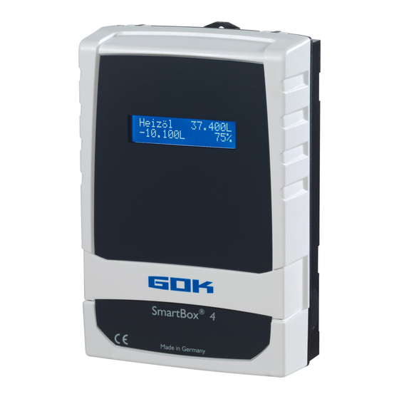
® ® SmartBox 4 / SmartBox 4 PRO INBETRIEBNAHME Bedienelemente und Display Die Geräteeinstellung erfolgt einmalig bei der Inbetriebnahme. Nach der Inbetriebnahme arbeitet das Anzeigegerät im Anzeigemodus mit geschlossenem Gehäusedeckel. Die Anzeige erfolgt in einem 2-zeiligen LCD-Display mit 2 x 16 Zeichen. Das Display hat eine blaue Hintergrundbeleuchtung (mit weißer Schrift), für beste Ablesbarkeit bei allen Lichtverhältnissen. -
Page 12: Programmierung
® ® SmartBox 4 / SmartBox 4 PRO PROGRAMMIERUNG Überfüllen des Tanks durch falsche Eingabewerte. Betriebsmedien können auslaufen. Diese: • sind gewässergefährdend, • sind entzündbare Flüssigkeiten der Kategorie 1,2 oder 3, • können sich entzünden und Verbrennungen verursachen, • können zu Sturzverletzungen durch Ausrutschen führen. Eingabe der Werte sorgfältig vornehmen! Die Eingabewerte bleiben auch bei Ausfall der Versorgungsspannung erhalten. - Page 13 4 / SmartBox 4 PRO Menü-Schritt Eingabefunktion Eingabewert Tank: 1 Auswahl des Tanks (Tank: 1 bis 4) zur Eingabe der SmartBox 4 Tank:_______ zugehörigen Werte (wird nicht angezeigt falls nur eine ® Sonde an SmartBox 4 PRO angeschlossen ist). 0.Exit Mit [Enter] zurück zum Anzeigemodus.
- Page 14 ® ® SmartBox 4 / SmartBox 4 PRO Menü-Schritt Eingabefunktion Eingabewert 3.Tankform Auswahl der Tankform mit [Enter] Linear Standard-Voreinstellung linearer Tank; rechteckiger Tank; stehender Zylinder; kellergeschweißter Stahltank Zylinder zylindrischer Tank bis 50 m³ (siehe auch alternativ Zyl. liegend > 50.000 L) liegender Zylinder; röhrenförmiger Tank; typische Bauform als Außentank oder Erdtank aus Stahl kugelförmiger Tank Kugelförmig...
- Page 15 Summenbestand + Prozentwerte Die Angabe fehlerhafter Schaltpunkte und die Verwechslung von Ein- und Ausschaltpunkt kann zur Überfüllung des Tanks oder zum Trockenlauf einer Pumpe führen! 7.Relais 1 Schaltfunktion Relais: SmartBox 4 Deaktiv Relais schaltet nicht. Ein ______% Aktiv Relais schaltet.
-
Page 16: Programmierbeispiele
Relais ist außer Funktion gesetzt durch Auswahl von Deaktiv oder Eingabe von 0% oder 0°C (jeweils bei Ein und Aus) ® 7.Exit SmartBox 4 PRO Mit [Enter] zurück zum Anzeigemodus 8.Exit Mit [Enter] zurück zum Anzeigemodus Nach Eingabe bzw. Auswahl der Menü-Schritte 1 bis 7 ist die Programmierung beendet. - Page 17 ® ® SmartBox 4 / SmartBox 4 PRO Beispiel 2: Erdtank zylindrisch liegend, für 100600 Liter Diesel, Innenhöhe 288.6 cm (Füllstand 54 cm) ® SmartBox 4 mit Pegelsonde Standard 0 bis 250 mbar Relais soll Trockenlaufschutz für die Pumpe geben (Ausschalten) Relais - EIN bei 99 % - AUS bei >...
-
Page 18: Sondereinstellungen
® ® SmartBox 4 / SmartBox 4 PRO Tanks mit Innenhülle Bei Tanks mit Innenhülle (z. B. zylindrisch liegende oder kellergeschweißte Tanks) müssen die Eingaben im Schritt „4.Tankvolumen“ und „5.Tankhöhe innen“ korrigiert werden. Beispiele: Wandstärke Innenhülle 0,5 cm Innenhöhe ca. 1 cm reduzieren und Volumen bei 10 m³ um 1,3 %, bei 20 m³... - Page 19 ® ® SmartBox 4 / SmartBox 4 PRO Menü-Schritt Einstellung Beschreibung/ Einstellung 13.Rundung Automatisch Standard-Voreinstellung Ungerundet Minimale Schrittweite Rundungs-Schrittweite je nach eingestelltem Volumen und Anzeigeeinheit mit [+]/ [-]Taste 100L auswählbar 200L 500L 1.000L 14.Exit Mit [Enter] zurück zum Anzeigemodus 15.Modem zurück Menü...
- Page 20 ® ® SmartBox 4 / SmartBox 4 PRO Menü-Schritt Einstellung Beschreibung/ Einstellung 22.Test Testfunktion/ Prüffunktion des akt. mA-Wertes der Strom Sonde: ADC: 7400=11.40 mA Bei nicht eingetauchter Pegelsonde sollte der Wert bei 4 mA sein. Toleranzbereich 3,7…4,3 mA. 23.Test Relais An die Relaiskontakte angeschlossene Geräte werden mit ein- bzw.
-
Page 21: Programmierung Fernüberwachungsfunktionen
® ® SmartBox 4 / SmartBox 4 PRO PROGRAMMIERUNG FERNÜBERWACHUNGSFUNKTIONEN Bei Anbindung an www.smart-inspector.com erfolgt dies über das Internet. ® Alternativ können die Einstellparameter für die Fernüberwachungs-Funktionen der SmartBox auch von einem beliebigen Handy per SMS mitgeteilt werden. Dies kann direkt vor Ort oder auch (später) z. - Page 22 ® ® SmartBox 4 / SmartBox 4 PRO Meldeereignis/ Meldegründe Ein Meldeereignis kann ausgelöst werden durch: Meldetext Meldegrund Info Zyklische Meldung nach n Tagen oder nach x % Rückgang des Füllstandes Info Tank 2 Meldung bei Betankungsbeginn (Niedrigstand) Betankung Meldung nach der Betankung, erfolgt ca. 60 Min nach Betankungsbeginn Tank 2 als Hochstandmeldung Manuelle...
-
Page 23: Liste Der Kommandos
® ® SmartBox 4 / SmartBox 4 PRO Alarm Der Zustand des Alarmeinganges (DIGITAL INPUT) wird in Klartext gemeldet, z. B. • kein Alarm • Alarm 1 Anlagenstörung Text Anlagenstörung ist änderbar (Befehl #A1) • Alarm 1 OK Gut-Meldung, d. h. Alarm 1 ist aufgehoben •... - Page 24 ® ® SmartBox 4 / SmartBox 4 PRO Komm- Parameter Beschreibung Standard- ando wert/ Vor- belegung Ändern der Verzögerungszeit für die Alarmkette [1…255] z. B. #Q=10 setzt die Verzögerungszeit auf 10 Minuten. Header-Text, der jeder SMS vorangestellt wird. Text 0 - 40 Tanküber- Zeichen max.
- Page 25 Die Unterschreitung führt zu einem Temperatur- Alarm an die Alarmkette #TA1.#TAn nur bei Tank-Löschung: Der Tank mit dieser Nr. wird aus der SmartBox 4 Tankregistrierung entfernt. Die hinteren Tanknummern rücken auf. (Der frühere Befehl #I löschte alle Tanks). Fern-Reset: Kaltstart-Befehl für Prozessor und...
- Page 26 Dienste-Telefonnummer für das T-Mobile-Netz (in Deutschland) #T=3400 Dienste-Telefonnummer für das Vodafone-Netz (in Deutschland) #T=6245 Dienste-Telefonnummer für das O2-Netz (in Deutschland) #H=MeineE-Mail@Adresse.de E-Mail-Adresse im Header voranstellen [Leerzeichen][+Header-Text] insgesamt max. 40 Zeichen Beispiel: #T=8000#H=info@gok-online.de HEL-Tank1, Hauptstr.7, 97340 MB 26 / 30 Artikel-Nr. 28 400 51 f...
-
Page 27: Bedienung
Das Produkt ist über örtliche Sammelstellen oder Wertstoffhöfe zu entsorgen. SERVICE Unter der Adresse www.gok-blog.de finden Sie Antworten auf besonders häufig gestellte Fragen aus den Themenbereichen Flüssiggasanlagen, Flüssiggas in der Freizeit, Ölfeuerungsanlagen und Tankmanagement. Artikel-Nr. 28 400 51 f... -
Page 28: Fehlerbehebung
® ® SmartBox 4 / SmartBox 4 PRO FEHLERBEHEBUNG Fehlercode Bedeutung Error E1 Eingestellter Wert ist ungültig. Messwert zu klein (I< 3,7 mA Sonde defekt). Error E2 Error E3 Messwert zu groß für Nullpunkt-Kalibrierung (Pegelsonde darf dabei nicht eingetaucht sein). Error E4 Messwert nicht plausibel. -
Page 29: Technische Daten
® ® SmartBox 4 / SmartBox 4 PRO Prüfung des Signals der Sonde: Mit Menü-Schritt „22.Test Strom“ prüfbar: ca. 3,7 bis 4,3 mA Bei 0 cm Füllstand Bei 1 m Wassersäule ca. 9 bis 11 mA (bei Pegelsonde Standard Messbereich 250 mbar) TECHNISCHE DATEN Anzeigegerät Wirkungsweise... -
Page 30: Liste Der Zubehörteile
® ® SmartBox 4 / SmartBox 4 PRO LISTE DER ZUBEHÖRTEILE Produktbezeichnung Verwendungshinweis Bestell-Nr. Daten-Transfermodul nachrüstbares Modul als Schnittstelle zur 28 851 00 analog 0 bis 5 Volt DTM-1 Datenübertragung z. B. für Gebäudesysteme Daten-Transfermodul nachrüstbares Modul als Schnittstelle zur 28 853 00 analog 4 bis 20 mA DTM-3 Datenübertragung z. - Page 31 ® ® SmartBox 4 / SmartBox 4 PRO Artikel-Nr. 28 400 51 f...
- Page 32 4 / SmartBox 4 PRO Regler- und Armaturen-Gesellschaft mbH & Co. KG Obernbreiter Straße 2-18 • 97340 Marktbreit / Germany Tel.: +49 9332 404-0 • Fax: +49 9332 404-43 E-Mail: info@gok-online.de • www.gok-online.de • www.gok-blog.de Artikel-Nr. 28 400 51 f...
- Page 33 TECHNICAL CHANGES ........................31 SERVICE ............................... 32 CERTIFICATE Our management system is certified according to ISO 9001, ISO 14001 and ISO 50001, see: www.gok-online.de/de/zertifikate/qualitaets-und-umweltmanagementsystem. Translation of the original operating instructions / part no. 28 400 57 c Version 12.2017 / Replaces version 03.2012...
-
Page 34: About The Manual
® ® SmartBox 4 / SmartBox 4 PRO ABOUT THE MANUAL • This manual is part of the product. • This manual must be observed and handed over to the operator to ensure that the component operates as intended and to comply with the warranty terms. •... -
Page 35: General Product Information
® ® SmartBox 4 / SmartBox 4 PRO Do not use this device for safety applications or emergency stop mechanisms or misuse it! Injuries and damage to health and property through misuse. You must observe the information contained in these instructions, especially regarding installation, start-up and maintenance. -
Page 36: Inappropriate Use
You will find a list of operating media with descriptions, the relevant standards and the country in which they are used in the Internet at www.gok-online.de/de/downloads/technische-dokumentation. Installation location • with protection type IP54, indoors and outdoors, if protected against the weather... -
Page 37: Assembly
® ® SmartBox 4 / SmartBox 4 PRO ASSEMBLY Before assembly, check that the product is complete and has not suffered any damage during transport. ASSEMBLY must be carried out by a specialised company. The specialised company and the operator must observe, comply with and understand all of the following instructions in this assembly and operating manual. -
Page 38: Electric Connection
Connection line between display unit and level probe Voltage Probe supply 20 V DC Connection Level probe connection – cable SmartBox 4 (LAN) Level probe - terminals Tank 1 Fig. SmartBox 4 Level probe 1 - terminals Tank 1 Fig... -
Page 39: Electrical Installation
® ® SmartBox 4 / SmartBox 4 PRO ELECTRICAL INSTALLATION ® ® SmartBox 4 PRO SmartBox Connection of supply voltage: Voltage: 230 V AC 50 Hz Connection: Terminals N + L to the display unit (cable not included in the delivery) Safety precautions for electrical components The functions and operating safety of the device are guaranteed only under the climatic conditions that are specified in TECHNICAL DATA. - Page 40 ® ® SmartBox 4 / SmartBox 4 PRO ® SmartBox SIM- card Excess voltage! Damage to components and device defect. No 230 V AC connections may be made to terminals 3 + 4 and 5 + 6 or probe input terminals 1 + 2! ®...
- Page 41 ® ® SmartBox 4 / SmartBox 4 PRO Connection of the fault signal input A switch contact (make or break contact) can be connected to the fault message input; for a burner fault signal, for example. If a fault occurs, an SMS text is sent to the administrator's mobile phone (with an approx.
- Page 42 ® ® SmartBox 4 / SmartBox 4 PRO ® Rain water reservoir - wiring example SmartBox Relay 7- 8 = break contact => pump safe to run dry Relay 9-10 = make contact => automatic backfeed control system Storm water reservoir Optional switch Drinking water network...
-
Page 43: Start-Up
® ® SmartBox 4 / SmartBox 4 PRO START-UP Operation elements and display The device is adjusted once when it is put into operation. After start-up the device operates in display mode with the top closed. The display is a two-line LCD display with 2 x 16 characters. The display has blue background lighting for best readability in all lighting conditions. -
Page 44: Programming
® ® SmartBox 4 / SmartBox 4 PRO PROGRAMMING Overfilling of the tank due to incorrect entry values. Operating media may leak. These: • are hazardous to water, • are category 1,2 and 3 inflammable liquids, • can ignite and cause burning, •... - Page 45 Menu Input function Input value Tank: 1 Select the tank (tank: 1 to tank: 4) to enter the SmartBox 4 corresponding values. (This step is not displayed if Tank:________ ® only one probe is connected to SmartBox 4 PRO.)
- Page 46 ® ® SmartBox 4 / SmartBox 4 PRO Menu Input function Input value 3.Tank shape Select Tank shape with [Enter] Linear Default setting linear tank, rectangular tanks, vertical cylinders, basement-welded steel tanks. Cylindric cylindrical tank to 50 m³ (see also alternative cyl. > horiz.
- Page 47 Entering incorrect switching points and mixing up the switch-on and shut-off point can lead to the overfilling of the tank or the dry running of a pump! 7.Relay 1 Switch function relay: SmartBox 4 Deactive The relay does not switch. Active The relay switches .
-
Page 48: Examples For Programming
® ® SmartBox 4 / SmartBox 4 PRO Menu Input function Input value Example of switch point setting for Active (with hysteresis): Enter switching points as % values from 01 - 99 (and/or enter as °C value from -99 to +99 only for probe with temperature measurement) deactive ... - Page 49 ® ® SmartBox 4 / SmartBox 4 PRO Example 2: Buried tank, cylindrical, horizontal, for 100,600 litres diesel oil Inner height 2.886 m, (fill level 54 cm) ® SmartBox 4 with standard level probe 0 - 250 mbar The relay to be used as an dry-run protection for a pump Relay - On at 99 % - 10 % - Off at <...
-
Page 50: Notes On Programming
® ® SmartBox 4 / SmartBox 4 PRO Tanks with inner shell For tanks with an inner shell (e.g. cylindrical horizontal or tanks welded together in the basement) the data in steps "4.Tank volume" and "5.Internal tank height" must be corrected. Examples: ... - Page 51 Delete Tank n Delete the registered Tank n (Tank 2, 3, 4) with T2<->T3 Replace Tank 2 for Tank 3 SmartBox 4 T2<->T4 Replace Tank 2 for Tank 4 T3<->T4 Replace Tank 3 for Tank 4 16.Sort Exit the menu...
- Page 52 SmartBox Activation of other indicators (and assignation of the respective tank numbers) Numbering the tanks: The contents indicator SmartBox 4 always has tank number 1. If other content indicators SmartBox 1, 2 or 3 (indicator) are to be connected “SERIAL ®...
-
Page 53: Programming The Remote Monitoring Functions
® ® SmartBox 4 / SmartBox 4 PRO PROGRAMMING THE REMOTE MONITORING FUNCTIONS If the device is linked to www.smart-inspector.com, this is done via the Internet. ® As an alternative, the setting parameters for remote monitoring functions of the SmartBox can also be transmitted via SMS by any mobile phone. - Page 54 ® ® SmartBox 4 / SmartBox 4 PRO Event causing the message The following events cause a message to be sent: Message text Reason for the message Info Cyclical message after n days or after x% reduction of fill level Info Tank 2 Message at start of fueling process (low level) Tank filling...
-
Page 55: List Of Commands
® ® SmartBox 4 / SmartBox 4 PRO Alarm The status of the alarm input (DIGITAL INPUT) is reported in plain text, e.g.: • kein Alarm (no alarm) • Alarm 1 Anlagenstörung the text Anlagenstoerung (Facility failure) can be changed (Command #A1) •... - Page 56 ® ® SmartBox 4 / SmartBox 4 PRO Comm- Parameter Description Standard / default value Text 0 – 40 Header-Text, introducing every SMS message. Tank characters monitoring max. Fill level message points: 10,30,15,07 [from..to] (always enter 4 Number 1 = Percentage increment for new values as 2- message, e.g.
- Page 57 ® ® SmartBox 4 / SmartBox 4 PRO Comm- Parameter Description Standard / default value Activate credit information: 0 - 101 OFF, no credit information, contract card or other prepaid card ON for prepaid card T-Mobile (*100# - in Germany DE) ON for prepaid card Vodafone (**100# - in Germany) SMS counter (recommended for...
- Page 58 Service telephone number for the Vodafone network (in Germany) #T=6245 Service telephone number for the O network (in Germany) #H=MyEmail@address.com Mention e-mail address first in the header [Leerzeichen][+Header-Text] insgesamt max. 40 Zeichen Example: #T=8000#H=info@gok-online.de HEL-Tank1, Hauptstr.7, 97340 MB 26 / 32 part no. 28 400 57 c...
-
Page 59: Operation
® ® SmartBox 4 / SmartBox 4 PRO Remote monitoring with the Smart Inspector system via Internet PC The Smart Inspector is a web-based database system for comfortable remote monitoring of tank data. ® Also in this case, the SmartBox sends the data via SMS. -
Page 60: Troubleshooting
® ® SmartBox 4 / SmartBox 4 PRO TROUBLESHOOTING Error code Significance Error E1 The set value is invalid. Error E2 Measured value too small I < 3,7 mA probe defective) Error E3 Measured value too great for zero point calibration (level probe must not be immersed). -
Page 61: Technical Data
® ® SmartBox 4 / SmartBox 4 PRO Checking the level probe signal: Can be checked through menu item 22: At 0 cm fill level approx. 3.7 - 4.3 mA. For 1 m water column approx. 9 - 11 m (standard level probe with measuring range 250 mbar). -
Page 62: List Of Accessories
® ® SmartBox 4 / SmartBox 4 PRO LIST OF ACCESSORIES Product description Information on application Order no. DTM-1 data transmission Retrofittable module as interface to data 28 851 00 module 0-5 V transmission, e. g. for the master control system of the building DTM-3 data transmission Retrofittable module as interface to data... -
Page 63: Warranty
® ® SmartBox 4 / SmartBox 4 PRO WARRANTY We guarantee that the product will function as intended and will not leak during the legally specified period. The scope of our warranty is based on Section 8 of our terms and conditions of delivery and payment. TECHNICAL CHANGES All the information contained in this assembly and operating manual is the result of product testing and corresponds to the level of knowledge at the time of testing and the relevant... -
Page 64: Service
4 / SmartBox 4 PRO SERVICE At the web address www.gok-blog.de you can find answers to frequently asked questions relating to the topics of LPG systems, liquefied gas for leisure time use, oil firing installations and tank management. Regler- und Armaturen-Gesellschaft mbH & Co. KG Obernbreiter Straße 2-18 •... - Page 65 MODIFICATIONS TECHNIQUES ......................31 SERVICE ............................... 32 CERTIFICATS Notre système de gestion est certifié selon ISO 9001, ISO 14001 et ISO 50001, voir : www.gok-online.de/de/zertifikate/qualitaets-und-umweltmanagementsystem. Traduction du mode d'emploi d'origine / référence 28 400 55 c Édition 12.2017 / Remplace l’édition 03.2012...
-
Page 66: À Propos De Cette Notice
® ® SmartBox 4 / SmartBox 4 PRO À PROPOS DE CETTE NOTICE • La présente notice fait partie intégrante du produit. • Cette notice doit être observée et remise à l’exploitant en vue d’une exploitation conforme et pour respecter les conditions de garantie. •... -
Page 67: Informations Générales Sur Le Produit
® ® SmartBox 4 / SmartBox 4 PRO Cet appareil ne doit pas être utilisé pour les applications de sécurité, les dispositifs d’arrêt d’urgence ou les applications non appropriées ! Une utilisation non appropriée peut entraîner des blessures, des dommages matériels, et nuire à... -
Page 68: Utilisation Non Conforme
Vous trouverez une liste des fluides d’exploitation utilisés avec indication de la désignation, de la norme et du pays d’utilisation sur Internet à l’adresse www.gok-online.de/de/downloads/technische-dokumentation. Lieu d'installation • avec type de protection IP54, en intérieur et en extérieur, à l’abri des intempéries Dysfonctionnement dû... -
Page 69: Montage
® ® SmartBox 4 / SmartBox 4 PRO MONTAGE Avant le montage, vérifier si le produit fourni a été livré dans son intégralité et s'il présente d'éventuelles avaries de transport. Le MONTAGE doit être exécuté par une entreprise spécialisée. L'entreprise spécialisée et l'exploitant sont tenus d'observer, de respecter et de comprendre l'ensemble des consignes figurant dans la présente notice de montage et de service. -
Page 70: Raccordement Électrique
Raccordement du câble de liaison entre appareil indicateur et la sonde de niveau Tension Alimentation de la sonde 20 V DC Connexion – Câble de connexion sonde SmartBox 4 (LAN) Sondes bornes citerne 1 fig. SmartBox 4 Sonde 1 - bornes citerne 1 fig. -
Page 71: Installation Eléctrique
® ® SmartBox 4 / SmartBox 4 PRO INSTALLATION ELÉCTRIQUE ® ® SmartBox 4 PRO SmartBox Tension d’alimentation, Tension : 230 V AC 50 Hz Connexion : bornes N et L sur l’appareil indicateur (câble non fourni) Consignes de sécurité relatives aux composants électriques Le bon fonctionnement et la sécurité... - Page 72 ® ® SmartBox 4 / SmartBox 4 PRO ® SmartBox Carte Surtension ! Endommagement des composants et défaut de l'appareil. Ne pas raccorder d'AC de 230 V aux clips 3 + 4 ou 5 + 6 ni aux clips d'entrée de sonde 1 + 2 ! ®...
- Page 73 ® ® SmartBox 4 / SmartBox 4 PRO Connexion de l’entrée d’information de perturbation Un contact de commutation (fermeture ou ouverture) peut être raccordé à l’entrée de signalisation de perturbation, par exemple pour le signal de défaut du brûleur. En cas de perturbation, le numéro de portable paramétré...
- Page 74 ® ® SmartBox 4 / SmartBox 4 PRO ® Citerne d’eau de pluie – exemple de câblage de SmartBox Relais 7- 8 = Ouverture (coupe) => Protect. fonct. à sec Réseau d’eau pompe potable Relais 9-10 = Contact fermeture => Commande de réappro.
-
Page 75: Mise En Service
L’afficheur possède un rétro-éclairage bleu qui permet une meilleure lisibilité dans toutes les conditions de lumière. ® 4 PRO : L’affichage ci-après apparaît pour la SmartBox 4 / SmartBox L’appareil se règle au moyen de trois petits boutons poussoirs bleus : Fioul... -
Page 76: Programmation
® ® SmartBox 4 / SmartBox 4 PRO PROGRAMMATION Débordement de la citerne par des valeurs saisies incorrectes. Les milieux peuvent fuir. Ils : • représentent un danger pour les eaux, • constituent des liquides inflammables de la catégorie 1, 2 ou 3, •... - Page 77 Menu Configuration Valeur d´entrée Citerne 1 Sélection du réservoir (réservoir : 1 à réservoir : 4) SmartBox 4 Cit. :________ pour saisir les valeurs correspondantes. (Cette étape ne s’affiche pas si une seule sonde est ® raccordée à la SmartBox 4 PRO).
- Page 78 ® ® SmartBox 4 / SmartBox 4 PRO Menu Configuration Valeur d´entrée 3.Forme cit Forme de citerne [Enter] Linéaire Configuration par défaut Citerne linéaire, rectangulaire ; cylindre debout, citerne d’acier soudée en cave. Cylindre Citerne cylindrique (voir aussi en alternative couché...
- Page 79 à la marche à vide d'une pompe ! 7.Relais 1 Fonction de commutation du relais: SmartBox 4 Désactivé le relais ne commute pas dans Actif le relais commute alors Marche force le relais à...
-
Page 80: Exemples De Programmation
Arrêt _____°C Mettez le relais hors fonction par Désactivé ou saisie de 0% ou 0°C (à MARCHE et ARRÊT) 7.SortieSmartBox 4 PRO Appuyez sur [Enter] pour revenir au mode d’affichage 8.Sortie Appuyez sur [Enter] pour revenir au mode d’affichage Après les étapes de saisie 1 à 7, la programmation est terminée. L’appareil passe automatiquement au mode d’affichage normal après confirmation par l’étape "8.Sortie"... - Page 81 ® ® SmartBox 4 / SmartBox 4 PRO Exemple 2 : Réservoir cylindrique enterré couché, pour 100.600 litres de gasoil Hauteur intérieure 288.6 m, (niveau 54 cm) ® SmartBox 4 avec sonde de niveau standard 0 à 250 mbar Relais doit donner protection contre la marche à sec pour la pompe (mise hors service) Relais - Marche <99% à...
-
Page 82: Réglage Spécial
® ® SmartBox 4 / SmartBox 4 PRO Citernes à enveloppe intérieure Sur les citernes à enveloppe intérieure (p. ex. citernes cylindriques horizontaux ou soudés sur place), il convient de rectifier les indications figurants aux étapes « 4. Volume citerne » et «... - Page 83 Affichage PIN, le cas échéant, modification du code 16.Tri retour Quitter le menu citernes Efface cit. n Efface la citerne n enregistrée (réservoir 2,3,4) SmartBox 4 T2<->T3 Permutation des citernes 2 et 3 T2<->T4 Permutation des citernes 2 et 4 T3<->T4 Permutation des citernes 3 et 4 16.Tri...
- Page 84 Procédez de la même façon pour chacun des autres appareils indicateurs. L’installation sur site est ainsi terminée. L'ordre des réservoirs affichés peut être modifié ultérieurement dans l'étape de menu 16.Tri citernes SmartBox 4 à changer. 20 / 32 référence 28 400 55 c...
-
Page 85: Programmation Des Fonctions De Tèlècontrole
® ® SmartBox 4 / SmartBox 4 PRO PROGRAMMATION DES FONCTIONS DE TÈLÈCONTROLE Vous pouvez l’effectuer depuis via internet en vous connectant à www.smart-inspector.com. ® Les paramètres de configuration des fonctions de télécontrôle de la SmartBox peuvent également se communiquer en SMS à l’aide d’un téléphone portable quelconque. Vous pouvez l’effectuer directement sur site ou encore (par la suite) depuis la centrale de l’entreprise, par exemple. - Page 86 ® ® SmartBox 4 / SmartBox 4 PRO Evènement déclenchant ou motif de l’information L’envoi d’une information peut être déclenché par : Information Motif de l’information Info Information cyclique après n jours ou baisse de niveau de x% Infos cit. 2 Information début de ravitaillement (niveau bas) Ravit.
-
Page 87: Liste Des Commandes
® ® SmartBox 4 / SmartBox 4 PRO Alarme L’état de l’entrée d’alarme (DIGITAL INPUT) est signalé en toutes lettres, par ex. • pas d’alarme • Alarme 1 Panne install. le texte "Panne install." peut être modifié (Commande #A1) • Alarme n OK ... - Page 88 ® ® SmartBox 4 / SmartBox 4 PRO Comm- Paramètre Description Valeur ande standard / par défaut #TA2= 2e + 3e téléphone mobile pour perturbation. 2e + 3e Ce champ … numéro de L’alarme momentanée est envoyée à ce n° donné est vierge en #TA3= téléphone...
- Page 89 ® ® SmartBox 4 / SmartBox 4 PRO Comm- Paramètre Description Valeur ande standard / par défaut #Pn= #P Modifier Les paramètres #P ci-dessus peuvent être réglés séparément : par ex. #P6=8 ou #P2=36h paramètres séparément #A1= Configuration: 0 (alarme se le contact est fermé) Configuration 0, panne alarme 1 :...
- Page 90 ® ® SmartBox 4 / SmartBox 4 PRO Comm- Paramètre Description Valeur ande standard / par défaut Consultation rapide de citerne à tout moment au portable appelant, p.ex. chauffeur de la citerne. Commande de lecture (Read) déclenche l’envoi d’un SMS d’information au portable appelant. Les compteurs journaliers standard de SMS d’information à...
-
Page 91: Fonctionnement
Adresse électronique dans l’en-tête [espace][+ caracteres d’en-tete] toujours 40 caracteres maxi. Exemple: #T=8000#H=info@gok-online.de HEL-Cit1, 12 rue d la Paix, 97340MB Télésurveillance par PC et Internet avec le système Smart-Inspector Smart-Inspector est un système de banque de données par Internet conçu pour la télésurveillance confortable de données de citernes. -
Page 92: Dépannage
® ® SmartBox 4 / SmartBox 4 PRO DÉPANNAGE Code Signification d’erreur Error E1 La valeur paramétrée est invalide. Error E2 La valeur de mesure est trop petite (I < 3,7 mA sonde défectueuse). Error E3 La valeur de mesure est trop grande pour le réglage du zéro (la sonde de niveau ne doit pas être immergée). -
Page 93: Données Techniques
® ® SmartBox 4 / SmartBox 4 PRO Contrôle du signal de sonde de niveau : Contrôlable à l’étape 22 de menu : au niveau 0 cm 3,7 - 4,3 mA env. pour une colonne d’eau de 1 m 9 - 11 mA env. (pour une sonde de niveau standard, plage de mesure 250 mbar) DONNÉES TECHNIQUES Appareil indicateur... -
Page 94: Liste Des Accessoires
® ® SmartBox 4 / SmartBox 4 PRO LISTE DES ACCESSOIRES Désignation du produit Conseil d’utilisation Réf. DTM-1 module de Module complémentaire d’interface pour la 28 851 00 transfert de données transmission de données, p. ex. pour la gestion 0-5 V technique de bâtiments DTM-3 module de Module complémentaire d’interface pour la... -
Page 95: Réparation
® ® SmartBox 4 / SmartBox 4 PRO RÉPARATION Le produit devra être renvoyé au fabricant pour contrôle si les mesures mentionnées sous DÉPANNAGE restent sans succès quant à la remise en service et qu’aucune erreur de dimensionnement n’a été commise. La garantie est annulée en cas d’interventions non autorisées. -
Page 96: Service
à l'adresse www.gok-blog.de. Regler- und Armaturen-Gesellschaft mbH & Co. KG Obernbreiter Straße 2-18 • 97340 Marktbreit / Germany Tel.: +49 9332 404-0 • Fax: +49 9332 404-43 E-Mail: info@gok-online.de • www.gok-online.de • www.gok-blog.de 32 / 32 référence 28 400 55 c... -
Page 97: Inhoudsopgave Certificaten
GARANTIE ............................. 31 TECHNISCHE WIJZIGINGEN ........................ 31 SERVICE ............................... 32 CERTIFICATEN Ons managementsysteem is gecertificeerd volgens ISO 9001, ISO 14001 en ISO 50001; zie: www.gok-online.de/de/zertifikate/qualitaets-und-umweltmanagementsystem. Vertaling van de originele gebruiksaanwijzing / artikelnr. 28 400 59 b Uitgifte 12.2012 / Vervangt uitgave 03.2012... -
Page 98: Over Deze Handleiding
® ® SmartBox 4 / SmartBox 4 PRO OVER DEZE HANDLEIDING • Deze handleiding maakt deel uit van het product. • Om het product volgens de voorschriften te kunnen gebruiken en eventueel een beroep te doen op de garantie moet deze handleiding in acht worden genomen en aan de gebruiker worden overhandigd. -
Page 99: Algemene Productinformatie
® ® SmartBox 4 / SmartBox 4 PRO Dit apparaat niet gebruiken voor veiligheidstoepassingen, noodstopapparatuur of onjuiste toepassingen! Letsel en schade aan gezondheid en materiaal door onjuiste toepassing. De in deze handleiding genoemde opmerkingen, met name voor inbouw, inbedrijfstelling en onderhoud, dienen beslist gevolgd te worden. Beschadigde of kapotte isolatie! Anders kan het leiden tot kortsluiting of schokken. -
Page 100: Onreglementair Gebruik
Montage- en gebruiksaanwijzing ‘Peilsonde’ in acht nemen! Een lijst van bedrijfsmedia met opgave van de aanduiding, de norm en het gebruiksland vindt u op www.gok-online.de/de/downloads/technische-dokumentation. Inbouwlocatie • met beschermingsgraad IP54, binnen en tegen het weer beschermd buiten Storing door overstroming! Het product is niet geschikt voor inbouw in overstromings-en risicogebieden. -
Page 101: Montage
® ® SmartBox 4 / SmartBox 4 PRO MONTAGE Controleer het product voor montage op transportschade en volledigheid. De MONTAGE, de INBEDRIJFSTELLING en het ONDERHOUD dienen door een vakman uitgevoerd te worden. Alle onderstaande aanwijzingen van deze montage- en gebruiksaanwijzing moeten door de installateur en de exploitant in acht worden genomen, nageleefd en begrepen. -
Page 102: Elektrische Aansluiting
Aansluiting kabel of de sonde – SmartBox 4 sonden - klemmen Tank 1 afbeelding SmartBox 4 PRO ssonde 1 - klemmen Tank 1 afbeelding ssonde 2 - klemmen Tank 2 ssonde 3 - klemmen Tank 3 ssonde 4 - klemmen ... -
Page 103: Elektrische Installatie
® ® SmartBox 4 / SmartBox 4 PRO ELEKTRISCHE INSTALLATIE ® ® SmartBox 4 PRO SmartBox Spanningsvoorziening, Spanning: 230 V AC 50 Hz Aansluiting: Klemmen N en L aan de indicator (kabel niet meegeleverd). Veiligheidsaanwijzingen elektrische componenten De werking en bedrijfszekerheid van het apparaat kunnen alleen gegarandeerd worden onder klimaatomstandigheden die bij TECHNISCHE GEGEVENS zijn gespecificeerd. - Page 104 1 en 2 wordt de tweepolige uitgangsklem „Serial Link Output“ (klemmen 3 + 4) met een 2-aderige kabel (bijv. 2 x 0,4 mm²) aan de klemmen 3 + 4 van de SmartBox 4 aangesloten (klemmen 3 3 en 4 4) – bij.
- Page 105 ® ® SmartBox 4 / SmartBox 4 PRO Overspanning! Beschadiging van onderdelen en defect van het apparaat. Op de sonde-ingangsklemmen 3 + 4, 5 + 6, 7 + 8 of 9 + 10 en op de klemmen 1 + 2 „ALARM INPUT“...
- Page 106 ® ® SmartBox 4 / SmartBox 4 PRO ® Regenwatertank - schakelvoorbeeld SmartBox Relay 7- 8 = Opener (onderbreker) => Droogloop- bescherming voor pomp Relay 9-10 = Sluitcontact => Autom. navulbesturing Regen-watertank Optioneel schakelaar Drinkwater toevoer Magneetventiel voor bijvulling Peilsonde Afvalwater Pompgroep ®...
-
Page 107: Inbedrijfstelling
® ® SmartBox 4 / SmartBox 4 PRO INBEDRIJFSTELLING Bedienelementen en display Het apparaat wordt eenmalig ingesteld tijdens de inbedrijfstelling. Na de inbedrijfstelling werkt het apparaat in de indicatiemodus met gesloten deksel. De indicatie gebeurt op een LCD- display met 2 x 16 tekens. Het display heeft een blauwe achtergrondverlichting voor een goede leesbaarheid bij alle lichtverhoudingen. -
Page 108: Programmering
® ® SmartBox 4 / SmartBox 4 PRO PROGRAMMERING Overvullen van de tank door verkeerde invoerwaarden. Bedrijfsmedia kunnen uitlopen. Deze: • zijn gevaarlijk voor het aquatisch milieu, • zijn ontvlambare vloeistoffen van categorie 3, • kunnen tot ontbranding en brandwonden leiden, •... - Page 109 Tank: 1 Keuze van de tank (tank: 1 tot tank: 4) waarvan de alleen bij waarden ingevoerd worden. Tank:_______ SmartBox 4 (Deze stap wordt niet weergegeven als er slechts één ® sonde op de SmartBox 4 PRO aangesloten is!) 0.Exit...
- Page 110 ® ® SmartBox 4 / SmartBox 4 PRO Stap Ingeeffunctie Ingegeven waarde 3.Tankform Vorm van de tank Linear Standaardinstelling vooraf Lineaire tank, rechthoekige tank, staande cilinder, in de kelder gelaste stalen tank Zylinder Cilindrische tank (zie ook alternatief cil. > 50 m³); liegend liggende cilinder;...
- Page 111 6.Anzeige Op de 1ste displayregel worden tanknaam/medium en Tanks voorraad weergegeven (bv. in liter). (Toon tanks) De weergave van de 2de regel kan gekozen worden: SmartBox 4 Weergavede- Vulruimte+procent tails Vulruimte+peil ____________ Procent+peil Voor stookolietanks is krachtens TRwS 791-2 in Duitsland een indicatie van de vrije ruimte vereist.
-
Page 112: Voorbeelden Voor Het Programmeren
Aus ______°C Relais buiten werking door deaktiv of ingeven van 0% of 0°C (steeds bij Ein en Aus) 7.Exit SmartBox 4 PRO [Enter] voert terug naar de indicatiemodus 8.Exit [Enter] voert terug naar de indicatiemodus Nadat de ingegeven stappen 1-7 zijn ingesteld is het programmeren beëindigd. Het apparaat gaat met de bevestiging van stap “8.Exit“... - Page 113 ® ® SmartBox 4 / SmartBox 4 PRO Voorbeeld 2: Ingegraven tank cilindrisch liggend, voor 100.600 liter diesel binnenwerkse hoogte 288.6 cm, (vulstand 54 cm) ® SmartBox 4 met 4 standaardpeilsonde 0 - 250 mbar Relais 1 voor de bescherming tegen drooglopen van pompen Relais 1 Relais 1 - AAN bei 99 % - UIT bei >...
-
Page 114: Aanwijzingen Voor Het Programmeren
® ® SmartBox 4 / SmartBox 4 PRO Tank met binnenbekleding Bij tanks met binnentank (bijv. cilindrische, liggende of in de kelder gelaste tanks) moeten de aangegeven van stap „4.Volume van de tank“ en „5.Binnenwerkse hoogte“ worden gecorrigeerd. Voorbeelden: Wanddikte binnentank 0,5 cm binnenwerkse hoogte ca. 1 cm reduceren en volume bij 10 m³... - Page 115 Het menu verlaten Tanks/Tri Tank n löschen Wist geregistreerde Tank n n (Tank 2, 3, 4) citernes (Clear n Tank) SmartBox 4 T2<->T3 Tank 2 met Tank 3 omwisselen T2<->T4 Tank 2 met Tank 4 omwisselen T3<->T4 Tank 3 met Tank 4 omwisselen 16.Sort.
- Page 116 (afhankelijk van de selectie / aanpassing van het menu 14.Toon tanks). Voor de andere indicatoren moet - na elkaar - dezelfde procedure worden gevolgd. De volgorde van de weergegeven tanks kan later worden gewijzigd in menu stap 16.Sort. Tanks SmartBox 4. 20 / 32 artikelnr. 28 400 59 b...
-
Page 117: Programmeren Van De Functies Voor De Controle Op Afstand
® ® SmartBox 4 / SmartBox 4 PRO PROGRAMMEREN VAN DE FUNCTIES VOOR DE CONTROLE OP AFSTAND Bij de verbinding met www.smart-inspector.com gebeurt dit via internet. Alternatief kunnen de instelparameters voor de functies voor controle op afstand van ® SmartBox ook met een willekeurige gsm per SMS worden meegedeeld. - Page 118 ® ® SmartBox 4 / SmartBox 4 PRO Melding / Oorzaken van de melding Een melding kan worden veroorzaakt door: Tekst van de Oorzaak van de melding melding Info Cyclische melding na n dagen of na x % teruglopende vulstand Info Tank 2 Melding bij begin van het vullen van de tank (laagste stand) Tank filling...
-
Page 119: Lijst Van De Commando's
® ® SmartBox 4 / SmartBox 4 PRO ontvangt van de extra indicator geen gegevens meer) Alarm De toestand van de alarmingang (DIGITAL INPUT - digitale input) wordt in verstaanbare taal gemeld bijv. • geen alarm • Alarm 1 Anlagenstörung Tekst Anlagenstörung kan gewijzigd worden (commando #A1) •... - Page 120 ® ® SmartBox 4 / SmartBox 4 PRO er op dit alarm geen verdere meldingen. leeg. Comm Parameter Beschrijving Standaard ando waarde vóór de vulling Wijzigen van de vertragingstijd voor de alarmketen, bijv. #Q=10 stelt de vertragingstijd in op 10 minuten. [1…255] Header-Tekst, waarmee iedere SMS begint.
- Page 121 ® ® SmartBox 4 / SmartBox 4 PRO Comm Parameter Beschrijving Standaard ando waarde vóór de vulling Mededelingen Tegoed activeren: 0 - 101 OFF, geen mededeling m.b.t. Tegoed, Abonnementskaart of andere Prepaid-Card ON voor Prepaid-Card D1 Xtra (*100#) ON voor Prepaid-Card D2 (**100#) SMS-teller (aanbevolen bij SIM- abonnementskaart!) 101 =...
- Page 122 Service-telefoonnummer voor het D2-net #T=6245 Service-telefoonnummer voor het O -net (in Deutschland) #H=MeineE-Mail@Adresse.de [spatie][+32 e-mail-adres vóór aan de Header zetten tekens voor Header] max. 40 Zeichen Voorbeeld: #T=8000#H=info@gok-online.de HEL-Tank1, Hauptstr.7, 97340 MB 26 / 32 artikelnr. 28 400 59 b...
-
Page 123: Bediening
® ® SmartBox 4 / SmartBox 4 PRO Controle op afstand met het Smart-Inspector-Systeem via Internet-PC De Smart-Inspector is een op het web gebaseerd databank-systeem voor een comfortabele controle van tankgegevens met afstandsbediening. ® De SmartBox zendt daarbij onveranderd de gegevens per SMS. Alle meldingen van deze installatie worden dan door de Smart-Inspector-server aangenomen, genoteerd en verder verwerkt. -
Page 124: Oplossing Van De Storing
® ® SmartBox 4 / SmartBox 4 PRO OPLOSSING VAN DE STORING Code van Betekenis de fout Error E1 Ingestelde waarde is ongeldig. Error E2 Gemeten waarde te gering (I < 3,7 mA sonde defect). Error E3 Gemeten waarde te groot voor ijking van het nulpunt (peilsonde mag daarbij niet zijn ondergedompeld). -
Page 125: Technische Gegevens
® ® SmartBox 4 / SmartBox 4 PRO Controle van het signaal van de peilsonde: Kan d.m.v. menustap 22 worden gecontroleerd: Bij 0 cm vulstand ca. 3,7 - 4,3 mA. Bij 1 m waterkolom ca. 9 - 11 mA (bij standaard peilsonde met meetbereik 250 mbar). TECHNISCHE GEGEVENS Indicator Werkingswijze... -
Page 126: Lijst Van Toebehoren
® ® SmartBox 4 / SmartBox 4 PRO LIJST VAN TOEBEHOREN Benaming van de Aanwijzing gebruiksdoel Bestelnr. producten DTM-1 Data-Transfer-Module Module die achteraf kan worden geïnstalleerd 28 851 00 0-5 V als interface voor de overdracht van gegevens bijv. voor de geleidingstechniek in het gebouw DTM-3 Data-Transfer-Module Module die achteraf kan worden geïnstalleerd 28 853 00... -
Page 127: Garantie
® ® SmartBox 4 / SmartBox 4 PRO GARANTIE Wij garanderen voor het product de juiste werking en dichtheid binnen de wettelijk voorgeschreven periode. De omvang van deze garantie is beschreven in § 8 van onze leverings- en betalingsvoorwaarden. TECHNISCHE WIJZIGINGEN Alle opgaven in deze montage- en gebruiksaanwijzing zijn het resultaat van productcontrole en komen overeen met de huidige stand van de kennis en de stand van de wetgeving en de toepasselijke normen op de datum van afgifte. -
Page 128: Service
4 / SmartBox 4 PRO SERVICE Op het adres www.gok-blog.de vindt u antwoorden op bijzonder vaak gestelde vragen over de thema's installaties met vloeibaar gas, vloeibaar gas in de vrije tijd, olieverbrandingsinstallaties en tankbeheer. Regler- und Armaturen-Gesellschaft mbH & Co. KG Obernbreiter Straße 2-18 •...
Need help?
Do you have a question about the SmartBox 4 and is the answer not in the manual?
Questions and answers