GOK SmartBox 1 Installation And Operating Manual
Hide thumbs
Also See for SmartBox 1:
- Assembly and operating manual (112 pages) ,
- Assembly and operating manual (140 pages) ,
- Assembly and operating instructions manual (112 pages)
Advertisement
Quick Links
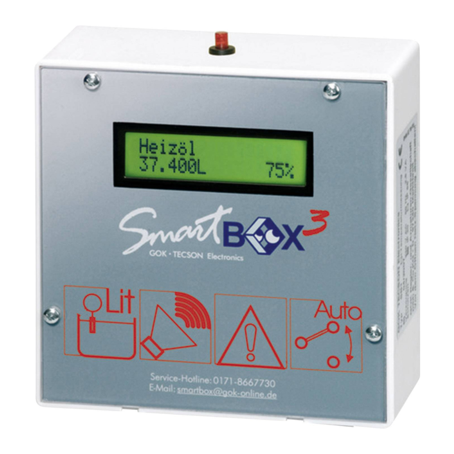
SmartBox 1 / SmartBox 2 / SmartBox 3
Electronic Content Indicator - Optionally with additional functions
GENERAL
The electronic tank management system SmartBox 1, SmartBox 2 and SmartBox 3 can be used
for monitoring of the liquids contained in unpressurized liquids tanks.
In addition to the registration of tank content, other functions can be implemented by system
enhancements, e.g. temperature measurement, data telecommunication, or connection to master
control systems of the building.
The SmartBox 2 has additional relay control functions, e.g. for activating external alarm devices,
solenoid valves, or the dry-run protection function of pumps.
The SmartBox 3 has relay control functions and an audible alarm for minimum level Indication.
When the acoustic alarm sounds, it can be switched off by pressing the 'Quit' key.
Thanks to its modular design, the system can be equipped with additional modules, e.g. with an
analog interface or a GSM module for telecommunication.
The indicated measurements are not gaged for invoicing.
The measuring probe is not a safety device, not even in connection with an electronic indicator.
Accordingly, it will not replace a limit monitoring indicator at the tank.
To operate the device as intended and to observe the warranty conditions, it is imperative that
you adhere to this Installation and Operating Manual and hand it over to the user.
DESIGN
The SmartBox 1 has an 8-digit LCD display and a measuring input for connecting the probe. The
SmartBox 2 has additionally 2 programmable relays with make and break switching output. The
SmartBox 3 has a programmable relay with make and break switching output and an acoustic
alarm for minimum level Indication. As a standard, the measuring probe can be installed with tank
connecting thread G1, G1½ or G2.
OPERATING MEDIA
Fuel oil EL
Diesel fuel DK
FAME (Biodiesel)
Hydraulic oil
Motor oil
Vegetable oil
Urea solution
acc. to DIN 51603-1
acc. to DIN EN 590
acc. to DIN EN 14214
e.g. AdBlue acc. to
DIN 70700
CONTENT
GENERAL
DESIGN
OPERATING MEDIA
IDENTIFICATION
INSTALLATION
START-UP
EXAMPLES FOR PROGRAMMING 6
OPERATION
PERFORMANCE CHECK
MAINTENANCE
REPAIR
ADDITIONAL TECHNICAL DATA 11
LIST OF ACCESSORIES
petroleum
alcohol
glycerin
glycol
brake fluid
water
Otto fuel
with fire point < 55° C
Article No. 28 100-
Version 12.2007
Page 1 of 12
Page:
1
1
1
2
2
5
10
10
10
10
11
fire point > 55° C
fire point > 55° C
only with SmartBox
in EX version
Advertisement

Related Manuals for GOK SmartBox 1


Summary of Contents for GOK SmartBox 1
- Page 1 Installation and Operating Manual and hand it over to the user. DESIGN The SmartBox 1 has an 8-digit LCD display and a measuring input for connecting the probe. The SmartBox 2 has additionally 2 programmable relays with make and break switching output. The SmartBox 3 has a programmable relay with make and break switching output and an acoustic alarm for minimum level Indication.
- Page 2 Article No. 28 100- Version 12.2007 Page 2 of 12 IDENTIFICATION Label Explanation Pursuant to EN 50081-1, EN 50082-1 and EN 61010-1 / A2 INSTALLATION Check the indicator and the probe element for transport damages before start of the installation. Indicator and measuring probe must only be installed and commissioned by qualified personnel.
- Page 3 Article No. 28 100- Version 12.2007 Page 3 of 12 Re-open the take-off line of the tank and reactivate the oil burner if applicable. Check the function of the oil burner. Indicator without cover lid Electrical Installation Connection line between indicator and probe unit: Voltage: Probe element 20 V DC Connection:...
- Page 4 Article No. 28 100- Version 12.2007 Page 4 of 12 Fuel oil tank - wiring example Smart Box1 SmartBox 1 MINUS PLUS ENTER oil tank measuring probe Rain water reservoir - wiring example SmartBox 2 SmartBox 2 Relay 1: 6-7 = break contact =>...
- Page 5 Article No. 28 100- Version 12.2007 Page 5 of 12 START-UP After the contents indicator has been installed, it can be started up. Before programming, you need to ascertain the tank data and enter the values into the right column Input value of the following table. Then, enter the values for the individual entry steps. Optionally, the device can also be programmed as explained in the enclosed Quick Guide.
- Page 6 Article No. 28 100- Version 12.2007 Page 6 of 12 ➜ ON: set with + / - ➜ Enter On: +0°C ___°C ➜ OFF: set with + / - ➜ Enter Off:+0°C Deactivate the relay or beeper via deactive ___°C or input of 0% or 0°...
- Page 7 Article No. 28 100- Version 12.2007 Page 7 of 12 Example 3 Well, 7.50 m maximum water level from ground of the well (fill level 4.20 m), relay switching function is desired. Probe TDS-6029 (measuring range 0 – 1000 mbar), indication in m water column. Step Entries Probe 1000 mbar...
- Page 8 Article No. 28 100- Version 12.2007 Page 8 of 12 cylindrical tank (optionally, see Cyl.>50m Cyl. horizontal cylinders; tubular tanks, max. 45 m typical shape for steel outdoor or buried tanks. Ball spherical tank; buried tanks with spherical basic shape; frequently plastic buried tank (GRP).
- Page 9 Article No. 28 100- Version 12.2007 Page 9 of 12 9.Offset Zero point adjustment (probe offset) Calibrat is indicated only after a calibration has been performed Default 10.Set h xxxx mm Possibility to enter reference height for 2-point-measurement, for a different probe measuring range, or if density is unknown.
- Page 10 Article No. 28 100- Version 12.2007 Page 10 of 12 Error messages Error code Significance Error E1 The set value is invalid Measured value too small (<3mA => probe defective) Error E2 Measured value too great for zero point calibration (probe must not be immersed) Error E3 Error E4 Not defined...
- Page 11 Article No. 28 100- Version 12.2007 Page 11 of 12 ADDITIONAL TECHNICAL DATA Indicator IP 30 or IP 65 acc. Supply voltage 230 V AC 50 Hz Degree of protection: to IEC 529 Power input: max. 2 VA 4 - 20mA ; U = 20V ;...
- Page 12 Article No. 28 100- Version 12.2007 Page 12 of 12 GOK Regler- und Armaturen-Gesellschaft mbH & Co. KG Obernbreiter Straße 2-16, D-97 340 Marktbreit +49 9332 404-0 Fax +49 9332 404-43 E-Mail: info@gok-online.de Internet: www.gok-online.de Art.-No. 28 100-57a...
Need help?
Do you have a question about the SmartBox 1 and is the answer not in the manual?
Questions and answers