Table of Contents
Advertisement
Quick Links
Assembly and operating manual
®
SmartBox
4 LAN / SmartBox
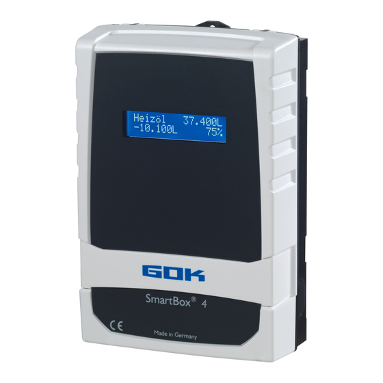
Electronic remote level gauge with network connection
CONTENTS
CERTIFICATE .......................................................................................................................................... 1
GENERAL PRODUCT INFORMATION .................................................................................................... 2
SAFETY ADVICE ..................................................................................................................................... 2
WARRANTY ............................................................................................................................................ 2
ABOUT THE MANUAL ............................................................................................................................. 3
INTENDED USE ...................................................................................................................................... 3
INAPPROPRIATE USE ............................................................................................................................ 4
USER QUALIFICATION ........................................................................................................................... 4
ASSEMBLY .............................................................................................................................................. 4
ELECTRIC CONNECTION ....................................................................................................................... 6
NETWORK CONNECTION ...................................................................................................................... 6
ELECTRICAL INSTALLATION ................................................................................................................. 6
START-UP ............................................................................................................................................... 8
TECHNICAL CHANGES ........................................................................................................................ 10
PROGRAMMING ................................................................................................................................... 10
EXAMPLES FOR PROGRAMMING ....................................................................................................... 14
NOTES ON PROGRAMMING ................................................................................................................ 16
CONFIGURING THE NETWORK COMMUNICATION ........................................................................... 19
OPERATION .......................................................................................................................................... 25
FUNCTION CHECK / MAINTENANCE ................................................................................................... 26
DISPOSAL ............................................................................................................................................. 26
RESTORATION ..................................................................................................................................... 26
TROUBLESHOOTING ........................................................................................................................... 26
PROBES AND ACCESSORY PARTS .................................................................................................... 27
LIST OF ACCESSORIES ....................................................................................................................... 28
TECHNICAL DATA ................................................................................................................................ 28
CERTIFICATE
Our management system is certified according to ISO 9001, ISO 14001 and
ISO 50001, see:
www.gok.de/qualitaets-umwelt-und-energiemanagementsystem.
Translation of the original operating instructions / part no. 28 410 57 b
®
4 LAN PRO
Version 12.2019 / Replaces version 12.2017
Advertisement
Table of Contents

Related Manuals for GOK SmartBox 4 LAN


Summary of Contents for GOK SmartBox 4 LAN
-
Page 1: Table Of Contents
TECHNICAL DATA ..........................28 CERTIFICATE Our management system is certified according to ISO 9001, ISO 14001 and ISO 50001, see: www.gok.de/qualitaets-umwelt-und-energiemanagementsystem. Translation of the original operating instructions / part no. 28 410 57 b Version 12.2019 / Replaces version 12.2017... -
Page 2: General Product Information
® ® SmartBox 4 LAN / SmartBox 4 LAN PRO GENERAL PRODUCT INFORMATION ® ® The electronic tank management system SmartBox 4 LAN, SmartBox 4 LAN PRO can be used for remote monitoring of the level in unpressurised tanks containing liquids. In addition to recording the tank content and remote data transfer, other functions can be implemented by system enhancements, e. -
Page 3: About The Manual
Comply with the “Level probe” assembly and operating manual! You will find a list of operating media with descriptions, the relevant standards and the country in which they are used in the Internet at www.gok.de/liste-der-betriebsmedien. Escaping, liquid operating media: • are hazardous to the aquatic environment •... -
Page 4: Inappropriate Use
® ® SmartBox 4 LAN / SmartBox 4 LAN PRO INAPPROPRIATE USE All uses exceeding the concept of intended use: Display unit: • changes to the product or parts of the product • installation in a potentially explosive area Probe: •... - Page 5 ® ® SmartBox 4 LAN / SmartBox 4 LAN PRO Damaged or destroyed insulation! Can result in short circuit or electric shock. Do not use the device if the insulation is damaged! Have new insulation installed by a specialised company! Selecting the installation location ®...
-
Page 6: Electric Connection
® ® SmartBox 4 LAN / SmartBox 4 LAN PRO ELECTRICAL INSTALLATION see corresponding instruction ® „FSA-W 4-20mA level gauge for SmartBox 1 – 4“. ELECTRIC CONNECTION Safety precautions for electrical components The functions and operating safety of the device are guaranteed only under the climatic conditions that are specified in TECHNICAL DATA. - Page 7 ® ® SmartBox 4 LAN / SmartBox 4 LAN PRO ® Connection of relay contacts on the display unit SmartBox 4 LAN ® The display unit SmartBox 4 LAN has two relay contact pairs for the connection of external control circuits or for activating external alarm or signal devices. In case of failure of the unit and if the fill level (and optionally temperature) is above the selected limit, the contacts of relay terminals 7 + 8 are closed, or 9 + 10 are open - see PCB in the display unit.
-
Page 8: Start-Up
® ® SmartBox 4 LAN / SmartBox 4 LAN PRO ® SmartBox 4 LAN PRO Excess voltage! Damage to components and device defect. No 230 V AC connections may be made to probe input terminals 3 + 4, 5 + 6, 7 + 8 and 9 + 10 and terminals 1 + 2! Connection of the fault signal input A switch contact (make or break contact) can be connected to the fault message input;... - Page 9 ® ® SmartBox 4 LAN / SmartBox 4 LAN PRO After the contents the display unit has been installed, it can be started up. Activating power supply: Keep away from the area of the 230V terminal! Heat oil Activate power supply – the following is displayed 100% ®...
-
Page 10: Technical Changes
® ® SmartBox 4 LAN / SmartBox 4 LAN PRO ® Rain water tank - wiring example SmartBox 4 LAN Relay 1: 7- 8 = break contact => pump safe to run dry Relay 2: 9-10 = make contact => automatic backfeed control system Storm water reservoir Optional... - Page 11 ® ® SmartBox 4 LAN / SmartBox 4 LAN PRO Setting a Press [ENTER] to open setup mode. parameter: Select the desired setting parameter via [PLUS]. Press [ENTER] to call up the value selection for the parameter. Set the value with [MINUS]/[PLUS], press [ENTER] to save. Quitting the You can quit the setup mode at any time.
- Page 12 ® ® SmartBox 4 LAN / SmartBox 4 LAN PRO Menu Input function Input value 3.Tank shape Select Tank shape with [Enter] Linear Default setting linear tank, rectangular tanks, vertical cylinders, basement-welded steel tanks. Cylinder cylindrical tank with arched ends horizontal horizontal tanks, tubular tanks typical shape for steel outdoor or buried tanks.
- Page 13 ® ® SmartBox 4 LAN / SmartBox 4 LAN PRO Menu Input function Input value 4.Tank Adjust the tank volume with [+] / [-] (100%). The default volume setting is 0 L. The value must be set. ___________L Please see a volume table for the highest value, if available.
-
Page 14: Examples For Programming
® ® SmartBox 4 LAN / SmartBox 4 LAN PRO Example of switch point setting for Active (with hysteresis): Enter switching points as % values from 01 - 99 (and/or enter as °C value from -99 to +99 only for probe with temperature measurement) deactive ... - Page 15 ® ® SmartBox 4 LAN / SmartBox 4 LAN PRO Example 2: Buried tank, cylindrical, horizontal, for 100.600 litres diesel oil Inner height 288.6cm, (fill level 54cm) ® SmartBox 4 LAN with 4 standard probes 0 - 250mbar The relay is to be used as an dry-run protection for a pump. Relay - On at >...
-
Page 16: Notes On Programming
® ® SmartBox 4 LAN / SmartBox 4 LAN PRO Tanks with inner shell For tanks with an inner shell (e.g. cylindrical horizontal or tanks welded together in the basement) the data in steps "4.Tank volume" and "5.Internal tank height" must be corrected. Examples: ... - Page 17 ® ® SmartBox 4 LAN / SmartBox 4 LAN PRO Menu Setting Description 13.Rounding Automatically Default settings: non rounded minimal increments Rounding increments in relation to the set volume set with [+] / [-] keys 100L 200L 500L 1.000L 14.Exit Press [Enter] to return to display mode 15.Network DHCP: YES...
- Page 18 6. Show tanks). Then, follow the same steps for the other display units. The order of the displayed tanks can be changed subsequently under menu step 16.Sort. Tanks SmartBox 4 LAN to be changed. 18 / 28 part no. 28 410 57 b...
-
Page 19: Configuring The Network Communication
® ® SmartBox 4 LAN / SmartBox 4 LAN PRO CONFIGURING THE NETWORK COMMUNICATION Network communication for the device is configured via the menu item "15.Network". By default, DHCP is enabled with "Yes". In this case, the device is assigned its IP address, subnet mask, gateway and DNS server address automatically by the router. - Page 20 ® ® SmartBox 4 LAN / SmartBox 4 LAN PRO Overfilling of the tank due to incorrect entry values. Operating media may leak. These: • are hazardous to water, • are category 1,2 and 3 inflammable liquids, • can ignite and cause burning, •...
- Page 21 ® ® SmartBox 4 LAN / SmartBox 4 LAN PRO Option D: Internet access ® PC and SmartBox 4 LAN are connected to a local network. The devices are visible in the intranet / LAN. The devices can be accessed from externally via the Internet through port forwarding in the router.
- Page 22 ® ® SmartBox 4 LAN / SmartBox 4 LAN PRO You can set the device and message parameters on this configuration page if you have change authorization with a password. The default password to access the configuration page is: tank This password can be changed on the configuration page.
- Page 23 ® ® SmartBox 4 LAN / SmartBox 4 LAN PRO Internet connection to an external system (Smart-Inspector.com) Convenient inventory management and alarm support with an external system server, e.g. www.Smart-Inspector.com. With this convenient solution the devices and the external system are continuously connected via the Internet.
- Page 24 ® ® SmartBox 4 LAN / SmartBox 4 LAN PRO CONFIGURATION OF EMAIL FUNCTION AND MESSAGING With the integrated e-mail function, the network device automatically and regularly reports its status (measured values and system status), as well as events (e.g. reserve) to the configured email destination mailbox.
-
Page 25: Operation
® ® SmartBox 4 LAN / SmartBox 4 LAN PRO Parameter Description Example / Presetting Critical limit Reporting threshold in %. e.g. 15% (range 0% ... 99%) When reached a message will be Time interval for repeating: send. 1 ... 15d or 1h, 4h, 12h or Options: deactivated. -
Page 26: Function Check / Maintenance
® ® SmartBox 4 LAN / SmartBox 4 LAN PRO FUNCTION CHECK / MAINTENANCE We recommend that you check the displayed litre values once per year to make sure that they are correct. For a simple check, pull the level probe up by its cable so that it hangs above the liquid. In this status the display device should show 0 litre (+ tolerance). -
Page 27: Probes And Accessory Parts
® ® SmartBox 4 LAN / SmartBox 4 LAN PRO Error code Significance Error E1 The set value is invalid Error E2 Measured value too small (I < 3.7mA probe defective) Error E3 Measured value too great for zero point calibration (probe must not be immersed) Error E4 Measured value not plausible. -
Page 28: List Of Accessories
IP68 acc. to EN 60529 Regler- und Armaturen-Gesellschaft mbH & Co. KG Obernbreiter Straße 2-18 • 97340 Marktbreit / Germany Tel.: +49 9332 404-0 • Fax: +49 9332 404-43 E-Mail: info@gok-online.de • www.gok.de • www.gok-blog.de 28 / 28 part no. 28 410 57 b...
Need help?
Do you have a question about the SmartBox 4 LAN and is the answer not in the manual?
Questions and answers