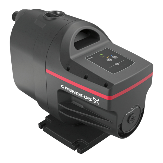
Grundfos SCALA1 SI Service Instructions Manual
Hide thumbs
Also See for SCALA1 SI:
- Installation and operating instructions manual (85 pages) ,
- Instructions manual (31 pages) ,
- Safety instructions and other important information (29 pages)
Table of Contents
Advertisement
Advertisement
Table of Contents

Summary of Contents for Grundfos SCALA1 SI
- Page 1 GRUNDFOS INSTRUCTIONS SCALA1 SI Service instructions...
- Page 3 SCALA1 SI English (GB) Service instructions ............... . 4...
-
Page 4: Table Of Contents
Removing the chamber stack ....7 The symbols and notes below may appear in Grundfos installation Removing the shaft seal ..... . 7 and operating instructions, safety instructions and service instructions. -
Page 5: Maintenance
Minor or moderate personal injury ‐ Before the pump is used for supplying drinking water, flush the pump thoroughly with clean water. ‐ Use spare parts approved by Grundfos. WARNING Electric shock Death or serious personal injury ‐ Check that the product is intact and not cracked. -
Page 6: Dismantling The Product
4. Dismantling the product Position part numbers (numbers in brackets) refer to section SCALA1 exploded view. 174b 184a 174c 4.1 Before dismantling the product Follow these steps before starting dismantling the pump. Disconnect the power supply to the motor. Remove power cable according to local regulations. 174a Gradually loosen the valves to release the pressure in the pump. -
Page 7: Removing The Chamber Stack
4.6 Removing the chamber stack Remove the plug (169) on the nameplate to access the shaft end. Find the locknut (67) at the non-drive end of the shaft. To remove the locking nut, place a 13-mm spanner on the nut and place the handle so that it rests against a flat surface to avoid spinning. -
Page 8: Removing The Control Box Cover
4.8 Removing the control box cover Always use an antistatic service kit when handling electronic components. This will prevent static electricity from damaging components. Remove the six pan-head Phillips screws (164a) that hold the the cover. 164a Opening lid and disconnecting the wires Disconnect the wires. -
Page 9: Removing The Motor
4.13 Removing the motor 5. Assembling the product 5.1 Fitting the motor stool and the flange Note that the motor stool is on the outer end of the motor Place the O-ring (150b) in the motor stool (156b). and the flange is on the inner end of the motor. Mount the motor (150) in the motor stool (156b). -
Page 10: Fitting The Shaft Seal
5.3 Fitting the shaft seal Do not touch the ceramic faces of the shaft seal. Assembling the chamber stack a. Shaft seal, stationary part (103) b. Shaft seal, rotating part (104) c. Diffusor, final (3) d. Diffusor (4a) e. Backward bushing for impeller (45a) f. -
Page 11: Connecting Thecapacitor To The Printed Circuit Board
5.6 Connecting the capacitor to the printed circuit board Put the capacitor (161) inside the control box and connect it to the printed circuit board (181b). Fitting the cover for hyraulic 5.10 Fitting the pressure switch Prepare the O-ring (174b), the inductive sensor (174c) and the three screws (175) that hold the pressure switch onto the Connecting the capacitor to the printed circuit board pump. -
Page 12: Additional Information
Hnom Qnom 55 °C T.amb.max IP X4D Tliq.max/Psyst.max: 45°C/0.8Mpa I(A) P1(W) Min. 0,01 Max. http://net.grundfos.com/qr/i/99735528 Example of nameplate Pos. Description Type designation Product number Serial number Production code (year and week) Max. head Nominal head Nominal flow rate Max. ambient temperature Enclosure class Max. -
Page 13: Scala1 Exploded View
6.6 SCALA1 exploded view SCALA1 3-25, 5-25 exploded view... - Page 14 164a 181a 181b 156a 181c 169a 169 100a 100b 156b 150b 174b 184a 174c 178a 174a 177a SCALA1 3-35, 3-45, 5-55 exploded view...
- Page 15 Centre Turkey Tel.: +387 33 592 480 29-33 Wing Hong Street & 68 King Lam GRUNDFOS Pumper A/S GRUNDFOS POMPA San. ve Tic. Ltd. Sti. Fax: +387 33 590 465 Street, Cheung Sha Wan Strømsveien 344 Gebze Organize Sanayi Bölgesi www.ba.grundfos.com...
- Page 16 99830441 10.2020 ECM: 1298119...


Need help?
Do you have a question about the SCALA1 SI and is the answer not in the manual?
Questions and answers