Table of Contents
Advertisement
Quick Links
M M M M S S S S - - - - 5 5 5 5 1 1 1 1 2 2 2 2 0 0 0 0
M M M M a a a a i i i i n n n n b b b b o o o o a a a a r r r r d d d d
M M M M a a a a n n n n u u u u a a a a l l l l
Ver 1.0
Trademarks Acknowledgment
The information presented in this publication has been carefully reviewed;
however, no responsibility is assumed for any inaccuracy. Specifications
are subject to change without notice.
¥
IBM, AT, XT are trademarks of International Business Machines
Corporation.
¥
Award is a registered trademark of Award Software Inc.
¥
Intel, Pentium, and Triton are trademarks of Intel Corporation.
¥
MS-DOS and Microsoft are trademarks of Microsoft Corporation.
¥
Other trademarks belong to their respective owners.
Advertisement
Table of Contents

Subscribe to Our Youtube Channel
Related Manuals for MATSONIC MS-5120


Summary of Contents for MATSONIC MS-5120
- Page 1 M M M M S S S S - - - - 5 5 5 5 1 1 1 1 2 2 2 2 0 0 0 0 M M M M a a a a i i i i n n n n b b b b o o o o a a a a r r r r d d d d M M M M a a a a n n n n u u u u a a a a l l l l Ver 1.0 Trademarks Acknowledgment...
-
Page 2: Table Of Contents
Table of Contents Overview ................4 Main Features .................. 5 Static Electricity Precautions............6 Unpacking the Mainboard ............... 7 Installation Procedures ............8 Mainboard Layout ................9 Jumper Settings................10 Jumpers................... 10 J2 Ð Power Supply Connector ..........11 Connectors:................11 USB1 Ð... - Page 3 Award BIOS Setup............15 CMOS Setup Utility ..............15 Standard CMOS Setup ..............15 BIOS Features Setup..............17 Chipset Features Setup ..............20 Power Management Setup ............. 21 PNP/PCI Configurations..............24 Load Setup Defaults ..............25 Integrated Peripherals ..............25 Supervisor/User Password .............
- Page 4 O O O O v v v v e e e e r r r r v v v v i i i i e e e e w w w w Congratulations on your decision to purchase MS5120 Mainboard of the MATSONIC series. This mainboard features the advanced capabilities of the VIA PCI chipset with high speed PCI local BUS and super I/O and it also provides the ultimate solution for optimizing the performance of your system.
-
Page 5: Overview
Overview Main Features The MS5120 Mainboard comes with the following high-performance features: VIA PCIsetª chipset; Flexible Processor Support; Ñ Onboard 321-pin ZIF socket supports Intel Pentium (P54C/P55C/MMX) CPU 75 ~ 233 MHz processors Ñ Cyrix/IBM 6x86-P120 + (100MHz) ~ 6x86-P200 + (150 MHz) processors/M2 series processors Ñ... -
Page 6: Static Electricity Precautions
System BIOS supports NCR810 SCSI BIOS firmware and Green feature function, Plug & Play Flash ROM ready. Static Electricity Precautions Static electricity can easily damage your MS-5120 Mainboard. The following procedures can help you to protect your mainboard from electrostatic discharge. -
Page 7: Unpacking The Mainboard
Overview Unpacking the Mainboard The MS-5120 Mainboard comes in a sturdy cardboard shipping carton. The carton contains the following items: ¥ MS-5120 Mainboard ¥ IDE, FDD, Serial port and Printer cables ¥ This UserÕs Manual The MS-5120 Mainboard is easily damaged by static electricity. Observe the following precautions while unpacking and installing the mainboard. - Page 8 Chapter 2 I I I I n n n n s s s s t t t t a a a a l l l l l l l l a a a a t t t t i i i i o o o o n n n n P P P P r r r r o o o o c c c c e e e e d d d d u u u u r r r r e e e e s s s s This chapter explains how to configure the MS5120 Mainboard's hardware.
-
Page 9: Installation Procedures
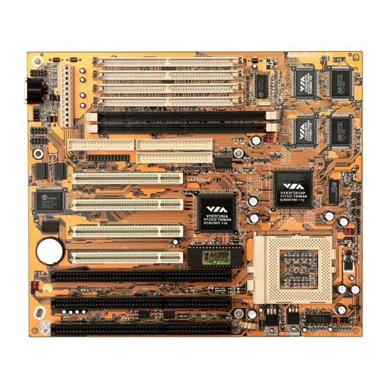
Installation Procedures Mainboard Layout USB1 COM1 COM2 PCI4 PCI3 PCI2 PCI1 SIMM4 SIMM3 SIMM2 SIMM1 IDE2 IDE1 Socket 3.3V DIMM2 DIMM1 Cache Cache JP10 JP11 Keylock Speaker Figure 2-1 Mainboard Component Layout... -
Page 10: Jumper Settings
MS5120 Mainboard Manual Jumper Settings Jumpers You can configure hardware options by setting jumpers on the motherboard. See figure 2-1 for jumper location. Some jumpers on the board have three metal pins with each pin representing a different function. To set a jumper, a black, white, or red cap containing metal contacts is placed over the jumper pin(s) according to the required configuration. -
Page 11: J2 Ð Power Supply Connector
Installation Procedures J2 Ð Power Supply Connector Connectors: Pin Description Pin Description COM1 Serial Port #1 Power Good Ground COM2 Serial Port #2 +5V DC Ground PRN1 Parallel Port +12V DC Ð5V DC IDE1 Primary IDE Port Ð12V DC 10 +5V DC IDE2 Secondary IDE Port Ground... -
Page 12: J8 Ð Power Led Connector
MS-5120 Mainboard Munual J8 Ð Keylock & Power LED J4 Ð Speaker Connector Connector Description Data Out Description N.C. LED Output Ground N.C. Ground Keylock Ground JP1 Ð Clear CMOS Setting Description Open Normal (default) Close Clear CMOS JP3A, B, C Ð CPU Speed Selectors... -
Page 13: Jp10 Ð Cpu Type Selectors
Installation Procedures JP10 Ð CPU Type Selectors Settings P54C P55C P1, P2 P2, P3 P1, P2 P2, P3 PS/2 Mouse Connector IR1 Ð Infra Red Description Pin Description IR In Mouse CLK Ground Ground N.C. IR Out Mouse Data +5V DC N.C. -
Page 14: How To Identify Your Bios
Chapter 3 H H H H o o o o w w w w t t t t o o o o I I I I d d d d e e e e n n n n t t t t i i i i f f f f y y y y Y Y Y Y o o o o u u u u r r r r B B B B I I I I O O O O S S S S Boot-up your computer. -
Page 15: Award Bios Setup
Award BIOS Setup A A A A w w w w a a a a r r r r d d d d B B B B I I I I O O O O S S S S S S S S e e e e t t t t u u u u p p p p The mainboard comes with the Award BIOS chip that contains the ROM Setup information of your system. - Page 16 MS5120 Mainboard Manual SIZE The hard disk size in Mega bytes. CYLS The cylinder number of the hard disk. HEAD The read/write head number of hard disk. The range is from 1 to 16. PRECOMP The cylinder number at which the disk drive changes the write timing. LANDZ The cylinder number that the disk drive heads (read/write) are seated when the disk drive is parked.
-
Page 17: Bios Features Setup
Award BIOS Setup BIOS Features Setup Moving around the BIOS and Chipset Features Setup programs (refer to the next section) works the same way as moving around the Standard CMOS Setup program. Users are not encouraged to run the BIOS and Chipset Features Setup programs. - Page 18 MS5120 Mainboard Manual Boot Sequence Allows the system BIOS to first try to boot the operating system from the selected disk drive. The options are: A, C (Default); C, A; C, CDROM, A; CDROM, C, A. Swap Floppy Drive When enabled, allows you to switch the order in which the operating system accesses the floppy drives during boot up.
- Page 19 Award BIOS Setup Typematic Rate Setting The term typematic means that when a keyboard key is held down, the character is repeatedly entered until the key is released. When this item is enabled, you may change the typematic repeat rate. The options are: Disabled (Default), Enabled.
-
Page 20: Chipset Features Setup
MS5120 Mainboard Manual Video BIOS Shadow When enabled, allows the BIOS to copy the video ROM code of the add-on video card to the system memory for faster access. The options are: Enabled (Default), Disabled. C8000-CBFFF to DC000-DFFFF Shadow When enabled, allows the BIOS to copy the BIOS ROM code of the add-on card to system memory for faster access. -
Page 21: Power Management Setup
Award BIOS Setup Power Management Setup Power Management When enabled, allows you to use Power Management features. The options are: Enabled and Disabled (Default). PM Control by APM Option No allows the BIOS to ignore the APM (Advanced Power Management) specification. Selecting Yes will allow the BIOS to wait for APM's prompt before it enters Doze mode, Standby mode, or Suspend mode. - Page 22 MS5120 Mainboard Manual The options are: DPMS Support (Default), V/H SYNC+Blank, and Blank Screen. MODEM Use IRQ This feature allows you to select the IRQ# to meet your modem's IRQ#. The options are: NA, 3 (Default), 4, 5,7, 9, 10 and 11. HDD Power Management Selecting Disabled will turn off the hard disk drive (HDD) motor.
- Page 23 Award BIOS Setup Suspend Mode When disabled, the system will not enter Suspend mode. The specified time option defines the idle time the system takes before it enters Suspend mode. The options are: Disabled (Default), 10, 20, 30, 40 sec, 1, 2, 4, 6, 8, 10, 20, 30, 40 min, and 1 hour.
-
Page 24: Pnp/Pci Configurations
MS5120 Mainboard Manual IRQ# Activity After the time period that you set in the Suspend Mode Feature, the system advances from Doze Mode to Suspend Mode, in which the CPU clock stops and the screen display is off. At this moment, if the IRQ activity that is defined as Primary occurs, then the system goes back to Full-on Mode directly. -
Page 25: Load Setup Defaults
Award BIOS Setup Reset Configuration Data When enabled, this feature allows the system to clear the last BIOS configuration data and reset them with the default BIOS configuration data. The options are: Enabled and Disabled (default). PCI IRQ Actived By If your IDE card is triggered by Edge, set it at Edge. - Page 26 MS5120 Mainboard Manual IDE Primary Master PIO Allows you to select first PCI IDE channel of the primary master hard disk mode or to detect it by the BIOS. The options are: Auto (Default), Mode 0, Mode 1, Mode 2, Mode 3, Mode 4.
- Page 27 Award BIOS Setup On-chip Secondary PCI IDE When enabled, allows the IDE drive to use the second channel of the primary IDE. The options are: Enabled (Default), Disabled. Onboard FDD Control When enabled, the floppy diskette drive (FDD) controller is activated. The options are: Enabled (Default), Disabled.
-
Page 28: Supervisor/User Password
MS5120 Mainboard Manual Onboard Parallel Mode Allows you to connect with an advanced printer I/O mode. The options are: SPP (Default), EPP, ECP, ECP/EPP. ECP Mode Use DMA 3 Allows you to select DMA channel 3 or 1 for the ECP printer mode. Parallel Port EPP Type Allows you to select the EPP parallel port. -
Page 29: Ide Hdd Auto Detection
Award BIOS Setup IDE HDD Auto Detection The IDE Hard Disk Drive Auto Detection feature automatically configures your new hard disk. Use it for a quick configuration of new hard disk drives. This feature allows you to set the parameters for up to four IDE HDDs. - Page 30 Appendix C C C C P P P P U U U U T T T T a a a a b b b b l l l l e e e e CPU BUS Clock Multiplier 75MHz 50MHz 90MHz 60MHz 100MHz 66MHz...
- Page 31 Award BIOS Setup...
Need help?
Do you have a question about the MS-5120 and is the answer not in the manual?
Questions and answers