Table of Contents
Advertisement
Quick Links
One Technology Way • P.O. Box 9106 • Norwood, MA 02062-9106, U.S.A. • Tel: 781.329.4700 • Fax: 781.461.3113 • www.analog.com
Evaluating the
FEATURES
3 common signal processing and conditioning blocks, a
preamplifier, an 8-pole filter, and an ADC driver integrated
to support a variety of demodulator applications
No external components required for proper operation
EVALUATION KIT CONTENTS
EVAL-ADAQ8088EBZ evaluation board
EQUIPMENT NEEDED
Bench supply of 2.7 V to 3.3 V
SMA cables
4-Port or 2-port network analyzer
AD9681-125EBZ evaluation kit
HSC-ADC-EVALEZ evaluation kit
Keysight 33600A generator
Allen Avionics LPF #F3056-7P7 (2 pieces)
PC running Windows®
PLEASE SEE THE LAST PAGE FOR AN IMPORTANT
WARNING AND LEGAL TERMS AND CONDITIONS.
Arrow.com.
Downloaded from
ADAQ8088
Dual-, Differential, Low-Pass Filter μModule
with Gain and ADC Driver
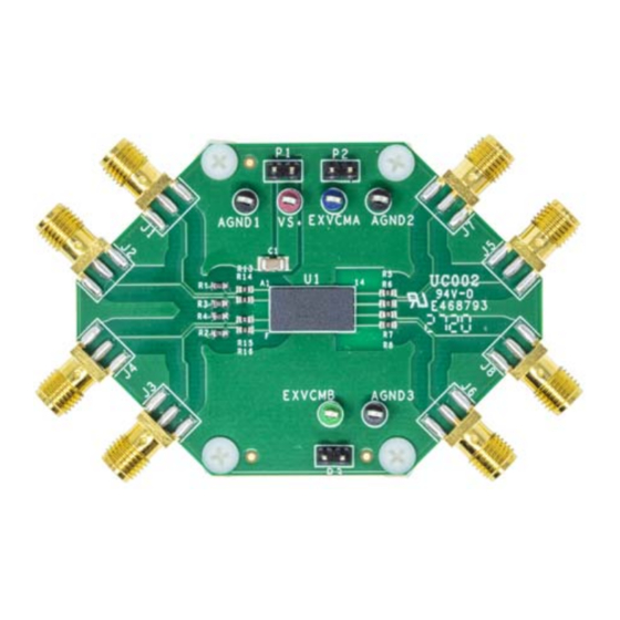
EVAL-ADAQ8088EBZ PHOTOGRAPH
Figure 1.
Rev. 0 | Page 1 of 12
EVAL-ADAQ8088EBZ
GENERAL DESCRIPTION
The EVAL-ADAQ8088EBZ evaluates the ADAQ8088 and requires
a 2.7 V to 3.3 V power supply for proper operation. The EVAL-
ADAQ8088EBZ accepts baseband differential in-phase/quadrature
(I/Q) inputs via Subminiature A (SMA)connectors (Jx) and
drives pipeline analog-to-digital converters (ADCs) via SMA
output connectors. The EVAL-ADAQ8088EBZ contains the
ADAQ8088 μModule, which is a dual-channel analog system in
package (SIP) that integrates three common signal processing
and conditioning blocks to support a variety of demodulator
applications and data acquisition applications. The device
integrates all active and passive components to form a complete
signal chain between the output of an I/Q demodulator and the
input to an ADC. For full details on the ADAQ8088, see the
ADAQ8088 data sheet, which must be consulted in conjunction
with this user guide when using the EVAL-ADAQ8088EBZ.
User Guide
UG-1825
Advertisement
Table of Contents

Subscribe to Our Youtube Channel
Related Manuals for Analog Devices EVAL-ADAQ8088EBZ


Summary of Contents for Analog Devices EVAL-ADAQ8088EBZ
-
Page 1: Features
ADC. For full details on the ADAQ8088, see the HSC-ADC-EVALEZ evaluation kit ADAQ8088 data sheet, which must be consulted in conjunction Keysight 33600A generator with this user guide when using the EVAL-ADAQ8088EBZ. Allen Avionics LPF #F3056-7P7 (2 pieces) PC running Windows® EVAL-ADAQ8088EBZ PHOTOGRAPH Figure 1. -
Page 2: Table Of Contents
Channel ...................6 General Description ................. 1 Calibration Procedure ..............6 EVAL-ADAQ8088EBZ Photograph ..........1 Evaluating the ADAQ8088 by Driving the AD9681 ADC ..7 Revision History ................2 Configuring the EVAL-ADAQ8088EBZ, AD9681-125EBZ, Evaluation Board Hardware ............3 ... -
Page 3: Evaluation Board Hardware
J1 and J2 SMA connectors, respectively, EVAL-ADAQ8088EBZ requires a supply voltage from 2.7 V to and the Q inputs (Q_INP and Q_INN) are connected through 3.3 V. The EVAL-ADAQ8088EBZ allows the user to set the the J4 and J3 SMA connectors, respectively. I_OUT_V... -
Page 4: Magnitude And Phase Response Measurements Using A Four-Port Network Analyzer
UG-1825 EVAL-ADAQ8088EBZ User Guide MAGNITUDE AND PHASE RESPONSE MEASUREMENTS USING A FOUR-PORT NETWORK ANALYZER MEASURING THE MAGNITUDE AND PHASE OF CALIBRATION PROCEDURE THE I-CHANNEL First ensure that the four-port network analyzer is calibrated using either the ECal (electronic calibration) module, or the To measure the magnitude and phase of the I-channel using a manual short, open, and load method. -
Page 5: Magnitude And Frequency Response Measurements Using A Two-Port Network Analyzer
Step 3 and Step 4 of the procedure in the I_INP as the To measure the frequency response at the I_OUTP Active Input section. output of the EVAL-ADAQ8088EBZ, take the following steps: Use an SMA cable to connect J7 of the EVAL- ADAQ8088EBZ to Port 2 of the network analyzer. -
Page 6: Measuring The Magnitude And Frequency Response Of The Q-Channel
Step 3 and Step 4 of the procedure in the Q_INP as the To measure the frequency response at the Q_OUTP Active Input section. output of the EVAL-ADAQ8088EBZ, take the following CALIBRATION PROCEDURE steps: Use an SMA cable to connect J8 of the EVAL- First ensure that the two-port network analyzer is calibrated ADAQ8088EBZ to Port 2 of the network analyzer. -
Page 7: Evaluating The Adaq8088 By Driving The Ad9681 Adc
40 Ω on the EVAL-ADAQ8088EBZ. C7 to C10, and R36 to R39. 33 Ω and 5 pF LPF on the EVAL-ADAQ8088EBZ Connect a jumper wire from Pin 3 to Pin 4 of T1. (still allows for optimization). Connect a jumper wire from Pin 1 to Pin 6 of T1. -
Page 8: Troubleshooting Tips
PC RUNNING VISUAL ANALOG AND SPI CONTROLLER USER SOFTWARE Figure 6. EVAL-ADAQ8088EBZ, AD9681-125EBZ, and HSC-ADC-EVALEZ Connections For further details on troubleshooting while evaluating TROUBLESHOOTING TIPS the ADAQ8088 by driving the AD9681 ADC, see the If the FFT appears normal but the performance is poor, check... -
Page 9: Evaluation Board Schematics And Artwork
1kΩ RB22 0.1µF 0.1µF RA11 1kΩ RA12 RB11 1kΩ RB12 0.1µF 0.1µF Figure 8. EVAL-ADAQ8088EBZ Feedback Resistor/Capacitor Placeholders Figure 9. EVAL-ADAQ8088EBZ Top Copper Layer Rev. 0 | Page 9 of 12 Arrow.com. Arrow.com. Arrow.com. Arrow.com. Arrow.com. Arrow.com. Arrow.com. Arrow.com. Arrow.com. - Page 10 UG-1825 EVAL-ADAQ8088EBZ User Guide Figure 10. EVAL-ADAQ8088EBZ GND Plane Figure 11. EVAL-ADAQ8088EBZ Power Plane Rev. 0 | Page 10 of 12 Arrow.com. Arrow.com. Arrow.com. Arrow.com. Arrow.com. Arrow.com. Arrow.com. Arrow.com. Arrow.com. Arrow.com. Downloaded from Downloaded from Downloaded from Downloaded from Downloaded from...
- Page 11 EVAL-ADAQ8088EBZ User Guide UG-1825 Figure 12. EVAL-ADAQ8088EBZ Bottom Copper Layer Rev. 0 | Page 11 of 12 Arrow.com. Arrow.com. Arrow.com. Arrow.com. Arrow.com. Arrow.com. Arrow.com. Arrow.com. Arrow.com. Arrow.com. Arrow.com. Downloaded from Downloaded from Downloaded from Downloaded from Downloaded from Downloaded from...
-
Page 12: Ordering Information
By using the evaluation board discussed herein (together with any tools, components documentation or support materials, the “Evaluation Board”), you are agreeing to be bound by the terms and conditions set forth below (“Agreement”) unless you have purchased the Evaluation Board, in which case the Analog Devices Standard Terms and Conditions of Sale shall govern. Do not use the Evaluation Board until you have read and agreed to the Agreement.
Need help?
Do you have a question about the EVAL-ADAQ8088EBZ and is the answer not in the manual?
Questions and answers