Fuji Electric ZFK8 Instruction Manual
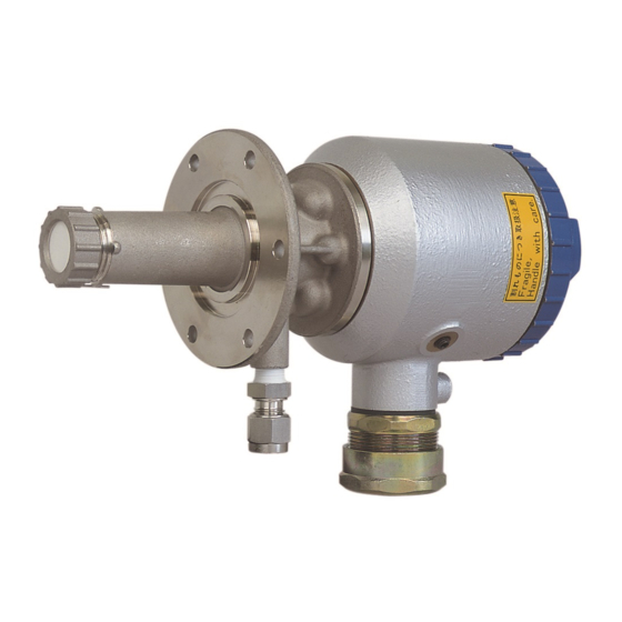
The direct insertion type zirconia oxygen analyzer detector
Hide thumbs
Also See for ZFK8:
- Instruction manual (35 pages) ,
- Instruction manual (35 pages) ,
- Instruction manual (123 pages)

Subscribe to Our Youtube Channel
Related Manuals for Fuji Electric ZFK8


Summary of Contents for Fuji Electric ZFK8
- Page 1 All manuals and user guides at all-guides.com Instruction Manual THE DIRECT INSERTION TYPE ZIRCONIA OXYGEN ANALYZER DETECTOR TYPE: ZFK8 INZ-TN5ZFK8d-E...
- Page 2 All manuals and user guides at all-guides.com PREFACE Thank you very much for your kind purchase of Fuji’s zirconia oxygen analyzer detector (Type ZFK 8). provements of the product. actually. refer to any time as requirfed. Type : Described in the nameplate put on the main body Date of manufacture : Described in the nameplate put on the main body Product nationality...
-
Page 3: Safety Precautions
All manuals and user guides at all-guides.com SAFETY PRECAUTIONS Prior to operating this detector, read this “Safety precautions” carefully for correct use. DANGER posed to die or get a serious injury. CAUTION medium injury or a minor injury and a physical damage is supposed to occur. PROHIBITION Precautions in installing and wiring DANGER... - Page 4 All manuals and user guides at all-guides.com Precautions in operation, stop, maintenance and check DANGER CAUTION bare hand. There is a fear of getting a burn. may result. PROHIBITION failure. Other precaution CAUTION be sure to ask the nearest dealer or Fuji adjustment serviceman for repair. If...
- Page 5 All manuals and user guides at all-guides.com CONTENTS ............................i ......................ii ....................................................................................................................................................................................................................................................................................................................8 ........................................................................................................................................................................ Maintenance and Check ........................................................................................................................
- Page 6 All manuals and user guides at all-guides.com INTRODUCTION General description of zirconia oxygen analyzer This zirconia oxygen analyzer makes use of the oxygen ion conductivity of solid electrolytes composed ) at high temperatures. If electrodes of platinum or the like are attached to both faces of a solid electrolyte and the faces are on the –...
-
Page 7: Description Of Each Component
All manuals and user guides at all-guides.com Description of each component CAUTION Furnace environment Air environment (Gas to be measured) (Reference gas) O-ring Thermo sticker Ceramic filter Terminal box Filter frame Measured gas Terminal box lid Quartz filter Heat insulating material Hexagon plug or reference gas inlet Ceramic heater... -
Page 8: Mounting Location
All manuals and user guides at all-guides.com MOUNTING Mounting location DANGER CAUTION or incorrect operation. and appliances bringing about electromagnetic induction trouble and electrostatic induction trouble) nearby the detector. Mounting method CAUTION... - Page 9 All manuals and user guides at all-guides.com 2.2.1 Mounting method of detector Caution in mounting Down Detector Down Down Mounting screw, plain washer, thermo sticker spring washer (accessory) - 3 locations Flow guide tube or ejector (ZTA) +45° -45° O-ring (accessory) Detector Gas flow Detector flange...
- Page 10 All manuals and user guides at all-guides.com (Designation of type: When 9th to 11th digits are 5A , 5B and 5C ) Packing (not included Furnace wall in scope of supply) Partition plate Tongue Arrow mark of flow guide tube Gas flow min.60mm ø15 (JIS5K-65A) Mating flange (not included...
- Page 11 All manuals and user guides at all-guides.com (Desingation of type : When 9th to 11th digits are 6D and 6E ) Fitted with high dust cover For high dust Gas outlet Gas outlet Gas flow Gas flow Gas flow Gas flow Inserting angle Down...
- Page 12 All manuals and user guides at all-guides.com PIPING Main body (calibration gas inlet) (1) Coupling a spanner after it cannot be turned any more by hand. (3) Frount ferrule Joint for calibration gas: (4) Back ferrule (2) Nut ø6mm or ø1/4inch teflon tube for piping Piping of reference gas inlet body.
-
Page 13: Piping Drawing
10/ 8 PTFE or 10/ 8 PTFE pipe or copper pipe pipe or copper pipe Flow guide tube (not supplied) (not supplied) Detector (ZFK8) AC power supply Gas temperature. 600ºC max. Rainproof flexible White conduit. Ref. air Black (Max. - Page 14 10/ 8 PTFE or 10/ 8 PTFE pipe or copper pipe pipe or copper pipe Flow guide tube (not supplied) (not supplied) Detector (ZFK8) AC power supply Gas temperature. 600ºC max. Rainproof flexible White Ref. air conduit.
- Page 15 (not supplied) 1500ºC max. Heater temperature drop Alarm Solenoid valve Copper pipe Copper pipe 10/ 6mm (not supplied) 10/ 8mm (not supplied) (not supplied) Detector (ZFK8) AC power supply White Rainproof flexible Black conduit. White (Max. 20m) Yellow Bule TM-1 +...
- Page 16 (not supplied) 1500ºC max. Heater temperature drop Alarm Solenoid valve Copper pipe Copper pipe 10/ 6mm (not supplied) 10/ 8mm (not supplied) (not supplied) Detector (ZFK8) AC power supply White Rainproof flexible Black conduit. White (Max. 20m) Yellow Bule TM-1 +...
- Page 17 All manuals and user guides at all-guides.com WIRING CAUTION is a fear of getting an electric shock. PROHIBITION...
-
Page 18: Before Wiring
All manuals and user guides at all-guides.com Before wiring noise preventive step......Element output For heater compensation conductor Thickness of vinyl insulating material (mm) Thickness of vinyl sheath (mm) Max. conductor resistance per unit length ( km) — Insulation resistance per unit length (M —... - Page 19 All manuals and user guides at all-guides.com Note for main ground (earth) line. Grounding terminal separately. The core should be poked from 0.5 to 1.0 mm. The core should be so as not to be seen or not to be come apart. Grounding terminal The crimping (vary by tools)
-
Page 20: Operation And Stop
All manuals and user guides at all-guides.com OPERATION AND STOP DANGER displayed and there is a fear of explosion. Start of operation starts its operation. calibrate by converting the output in a stabilized state into oxygen concentration according to the standard Stop of operation... -
Page 21: Maintenance And Check
All manuals and user guides at all-guides.com MAINTENANCE AND CHECK CAUTION burn. is not displayed fully and an accident or failure could come about. PROHIBITION Check every 6 months. Check items as a rough standard by converting the output in a stabilized state into oxygen concentration according to the standard output table of Check for looseness of cable gland. -
Page 22: Maintenance
All manuals and user guides at all-guides.com Maintenance gas and the amount of dust. standard............................................. 6.2.1 Replacement of Sensor unit Groove for the O-ring O-ring Sensor unit (1) Black (6) Blue (3) Red Grounding wire Pan head screw with washers screw: M4 (4 pieces) - Page 23 All manuals and user guides at all-guides.com Reflector frame. Ceramic filter Filter frame fully in the air. brush. CAUTION...
- Page 24 All manuals and user guides at all-guides.com Standard output of detector Detector output Detector output Detector output concentration concentration concentration...
- Page 25 All manuals and user guides at all-guides.com Arrangement Description (Procured type) Consumable Consumable Calibration gas inlet (for 6mm tube) procurement part Calibration gas inlet procurement part Thermo sticker procurement part (for 6mm tube) procurement part procurement part procurement part procurement part Type designation digits Inserting length For general use...
-
Page 26: Troubleshooting
All manuals and user guides at all-guides.com TROUBLESHOOTING CAUTION fare of an accident or injury. Troubles Probable causes Check procedures (normal values) tube interior ness of mounted part. and airtightness of mounted part. tion gas over to span calibration gas and vice versa if it takes response. - Page 27 All manuals and user guides at all-guides.com APPENDIX Operating temperature: General Specifications −10 to +60ºC for Primary detecting ele- Measuring object: Oxygen in noncombustible gas ment Measuring method: −5 to +100ºC for ejector section Directly insert type zirconia system 125ºC or less at detector flange surface Measuring range: 0 to 2 ···...
- Page 28 All manuals and user guides at all-guides.com Converter specification (ZKM) Output signal hold: Output signal is held during calibration, Concentration value indication: processing recoverable sensor, process- Digital indication in 4 digits ing diagnosis of sensor, warm-up, PID Contact output signal: auto tuning, under set up maintenance (1) Contact specification;...
-
Page 29: Power Supply
All manuals and user guides at all-guides.com 8.2.1 Detector 8.2.2 Replacement sensor unit 4 5 6 7 8 9 10 11 12 13 14 15 16 Power supply Code symbols Description 100 to 120V AC ZFK8YY15-0Y0YY-0YY Cal. gas inlet For ø6mm tube (SUS) 200 to 240V AC ZFK8YY35-0Y0YY-0YY For ø1/4 inch tube (SUS) -
Page 30: Device Composition
All manuals and user guides at all-guides.com 8.2.4 Converter 3 4 5 6 7 8 3 4 5 6 7 8 9 10 11 12 Description Description Connectable devices Construction For ZKM IP66 IP67 Types Bench type For R thermocouple Output signal Conduit length Cable length... - Page 31 All manuals and user guides at all-guides.com Approx.132 ø80 Approx.62 Approx.130 ø67 Heat insulating cover (as specified) Terminal box 6-ø6 EXTERNAL CONNECTION DIAGRAM Heater Thermocouple Element output Filter Black / White/ red / White/ yellow / blue 2-core wire 4-core wire Ground-wire Exclusive cable Screw: M4...
- Page 32 All manuals and user guides at all-guides.com ø155 Approx. 40 Approx. L ø130 ø67 Gas inlet Z F K 8 R 5 - 5 B 3 6-M5 Gas outlet detector side Code 11th 0.5 0.75 1.0 L (m) MASS (as specified) Approx.(kg) 8-ø15 Oxygen detector...
- Page 33 All manuals and user guides at all-guides.com 4-Rc1/4 with plug Blow down air inlet When mounting, select one of blow inlets on the upper side 8 - ø19 (for prevention of drain) MTG. hole Flange: JIS 5K80A FF ZFK MTG. position Packing Z F K 8 R 5 - 6 D...
- Page 34 All manuals and user guides at all-guides.com 4-Rc1/4 with plug Blow down air inlet When mounting, select one of blow inlets on the upper side 8 - ø19 (for prevention of drain) MTG. holes Flange: JIS 5K80A FF ZFK MTG. position Packing longate Z F K 8 R...
- Page 35 All manuals and user guides at all-guides.com Instrumentation & Sensors Planning Dept. 1, Fuji-machi, Hino-city, Tokyo 191-8502, Japan http://www.fujielectric.com Phone: +81-42-514-8930 Fax: +81-42-583-8275 http://www.fujielectric.com/products/instruments/...
Need help?
Do you have a question about the ZFK8 and is the answer not in the manual?
Questions and answers