Fuji Electric ZFK8 Series Instruction Manual
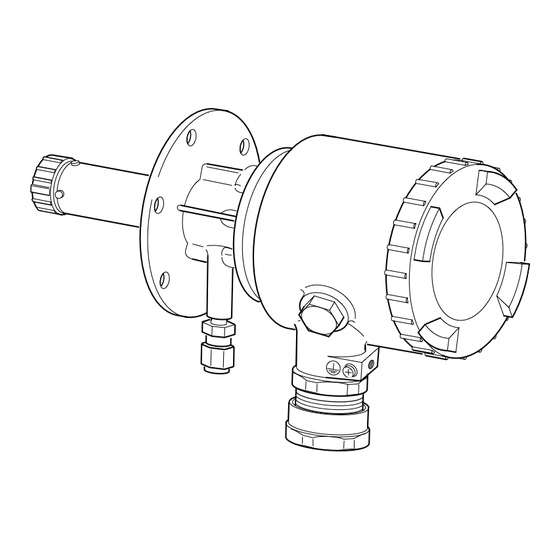
The direct insertion type zirconia oxygen analyzer detector
Hide thumbs
Also See for ZFK8 Series:
- Instruction manual (36 pages) ,
- Instruction manual (35 pages) ,
- Instruction manual (35 pages)

Subscribe to Our Youtube Channel
Related Manuals for Fuji Electric ZFK8 Series


Summary of Contents for Fuji Electric ZFK8 Series
- Page 1 Instruction Manual THE DIRECT INSERTION TYPE ZIRCONIA OXYGEN ANALYZER DETECTOR TYPE: ZFK8 INZ-TN5ZFK8b-E...
-
Page 2: Preface
Related instruction manuals Direct insertion type zirconia oxygen analyzer converter (Type : ZKM) ......... INZ-TN1ZKM Direct insertion type zirconia oxygen analyzer-use ejector (Type : ZTA) ........ INZ-TN1ZTA © Fuji Electric Systems Co., Ltd. 2008 NOTE Issued in Aug , 2008 •... -
Page 3: Safety Precautions
SAFETY PRECAUTIONS Prior to operating this detector, read this “Safety precautions” carefully for correct use. • In the precautions shown here, important contents on safety are included. So, be sure to observe them. The safety precautions have been ranked into “DANGER” and “CAUTION”. If this apparatus is abused, a dangerous condition could come about and it is DANGER supposed to die or get a serious injury. - Page 4 Precautions in operation, stop, maintenance and check DANGER: • In case where combustible gas is contained in the measured gas, check the gas composition and specifi cations carefully before using. Otherwise, the original performance is not displayed, and there is a fear of explosion. CAUTION: •...
-
Page 5: Table Of Contents
CONTENTS PREFACE ............................i SAFETY PRECAUTIONS ......................ii Introduction ..........................1 General description of zirconia oxygen analyzer ................1 Device confi guration of direct insertion type oxygen analyzer ...........1 Description of each component ....................2 Check of type ..........................2 Check of delivered articles ......................2 Mounting .......................... -
Page 6: Introduction
INTRODUCTION General description of zirconia oxygen analyzer This zirconia oxygen analyzer makes use of the oxygen ion conductivity of solid electrolytes composed mainly of zirconia (ZrO ) at high temperatures. If electrodes of platinum or the like are attached to both faces of a solid electrolyte and the faces are on the conditions of different oxygen partial pressures, an electrochemical reaction causes an electromotive force between both the electrodes. -
Page 7: Description Of Each Component
Description of each component CAUTIONS • The operating temperature of detector (tip of ceramic heater) is about 800°C and the surface temper- ature is also very high. So, never touch it by bare hand. Otherwise, there is a fear of getting a burn. Especially when a ceramic fi... -
Page 8: Mounting
MOUNTING Mounting location DANGER • This product has no explosion-proof specifi cation. Don’t use the product in an explosive gas environment. If used, a serious trouble such as a fi re or explosion might occur. CAUTIONS • Install this product at a place compatible with the following conditions. The use of it at a place not conforming the installation conditions specifi... - Page 9 2.2.1 Mounting method of detector Caution in mounting • Never mount the detector with the tip turned upward or downward. A failure of the detector may result. Down Detector Down Down Mounting screw, plain washer, thermo sticker spring washer (accessory) - 3 locations Flow guide tube or ejector (ZTA) +45°...
- Page 10 2.2.2 Mounting method of fl ow guide tube (Designation of type: When 9th to 11th digits are 5A■ ■ , 5B■ ■ and 5C■ ■ The fl ange of fl ow tube has mounting holes at 8 locations. These holes are available for regulating an in- fl...
- Page 11 2.2.3 Mounting method of high dust-use fl ow guide tube (Desingation of type : When 9th to 11th digits are 6D and 6E ) Mount the tube so that the gas outlet turns downward relative to the gas fl ow as shown below. Fitted with high dust cover For high dust Gas outlet...
-
Page 12: Piping
PIPING Piping of calibration gas Main body As the piping material, use a tefl on-made ø6mm or ø1/4inch tube. (calibration gas inlet) • From the coupling attached to the detector, remove (2) nut, (1) Coupling (3) front ferrule and (4) back ferrule, put them through to the ø6mm or ø1/4inch tefl... -
Page 13: Piping Drawing
Piping drawing Flow guide tube system (with valve) Reduction valve Rc1/4 (unnecessary when supply air pressure is Solenoid valve (upper side blow port should be selected) 200 to 300kPa) (not supplied) Blow-down, 200 to 300kPa Supply air 15ASGP 15ASGP Rainproof cover tube equivalent tube equivalent or ø10/ø8 PTFE... - Page 14 Flow guide tube system Reduction valve Rc1/4 (unnecessary when supply air pressure is Solenoid valve (upper side blow port should be selected) 200 to 300kPa) (not supplied) Blow-down, 200 to 300kPa Supply air 15ASGP 15ASGP Rainproof cover tube equivalent tube equivalent or ø10/ø8 PTFE or ø10/ø8 PTFE pipe or copper pipe...
- Page 15 Ejector system (with valve) Flowmeter Reduction valve (ZBD) Ejector (ZTA) (unnecessary when supply air pressure Ejector (5 to 10L/min) is 200 to 300kPa ) Joint Supply air Power supply Copper pipe ø6/ø4mm Gas temperature. (not supplied) 1500ºC max. Heater temperature drop Alarm Solenoid valve Copper pipe...
- Page 16 Ejector system Flowmeter Reduction valve (ZBD) Ejector (ZTA) (unnecessary when supply air pressure Ejector (5 to 10L/min) is 200 to 300kPa ) Joint Supply air Power supply Copper pipe ø6/ø4mm Gas temperature. (not supplied) 1500ºC max. Heater temperature drop Alarm Solenoid valve Copper pipe Copper pipe ø10/ø6mm...
-
Page 17: Wiring
WIRING CAUTIONS • In the case of the wiring work, be careful not to drop foreign matters including wire chips inside the product. Otherwise, this might cause a fi re, failure or malfunction. • Connect a power source compatible with the rating. Connection of a power source not conforming to the rating may cause a fi... -
Page 18: Before Wiring
Before wiring Put a cable (6 cores in all) connected between detector and converter into a piping tube for protecting the cable. Also, put the cables for R thermocouple and element output away from the power cable to take a noise preventive step. -
Page 19: Mounting Of Conduit
Connect the protective grounding to one of the two terminals in the fi gure below. (Class D (Class 3) grounding, grounding resistance: 100Ω or less) Note • Use the cable more than 0.75mm for main ground (earth) line. • For solderless terminal , doubly caulk the core and the sheath Grounding Grounding terminal... -
Page 20: Operation And Stop
OPERATION AND STOP DANGER • In case where combustible gas is contained in the measured gas, make sure of the gas composition and specifi cations carefully before using this product. Otherwise, the original performance is not displayed and there is a fear of explosion. Start of operation •... -
Page 21: Maintenance And Check
MAINTENANCE AND CHECK CAUTIONS • Do the work in a condition where the main power supply has been turned off. If the work is done while current is fl owing, there is a fear of getting an electric shock. • The operation temperature of the detector (tip of the ceramic heater) is about 800°C and the surface temperature is also very high. -
Page 22: Maintenance
Maintenance The replacing intervals of sensor unit, ceramic fi lter and O-ring, and the maintenance periods of fl ow guide tube and sampling probe differ depending on the working conditions including the components of measured gas and the amount of dust. The replacing intervals in a general conditions are shown below. - Page 23 6.2.2 Replacement of ceramic fi lter (1) After turning “OFF” the power of the detector, lower the surface Reflector temperature of the tip (at the ceramic fi lter side) by cooling down fully with the air. (2) After having been cooled down fully, remove the fi lter frame from the detector, take the ceramic fi...
-
Page 24: Standard Output Of Detector
Standard output of detector For the output voltage of the detector, refer to the standard output table below. Standard output table (Reference) Oxygen Detector output Oxygen Detector output Oxygen Detector output concentration (Unit: mV) concentration (Unit: mV) concentration (Unit: mV) (Vol%) (Vol%) (Vol%) -
Page 25: Arrangement
Arrangement Description Classifi cation Part No. for procurement Remark (Procured type) Ceramic fi lter Consumable *ZZPZFK5-TK750201P1 Detector O-ring (P38) Consumable *ZZPZFK5-8552836 Viton screw with washer (M3×8): Sensor unit for replacement Spare parts According to designation of type in 4 pcs. Item. -
Page 26: Troubleshooting
TROUBLESHOOTING CAUTIONS • If a failure should occur which cannot be judged even if referring to the operation manual, be sure to ask the nearest dealer or Fuji adjustment serviceman for repair. If disassembled carelessly, there is a fare of an accident or injury. Troubles Probable causes Check procedures (normal values) -
Page 27: Appendix
APPENDIX Specifi cation • Main materials of gas-contacting parts: Detector; Zirconia,SCS14, SUS316, platinum 8.1.1 General Flow guide tube; SUS304 or SUS316 Ejector (general use); SUS316, SUS304 • Measuring object: Oxygen in noncombustible gas Ejector; (for high temperature) SiC, SUS316, • Measuring method: Direct insertion type zirconia system SUS304 •... - Page 28 • Heater OFF • Finish color: Small case (IP66): Case: Silver • Blow down (option) Cover: Pantone Cool Gray IC-F • Inhibition of calibration Large case (IP67): • Calibration start Case: Munsell 6PB 3.5/10.5 (blue) • Range change Cover: Silver •...
-
Page 29: Designation Of Type (Code Table)
Designation of type (code table) 8.2.1 Detector 8.2.2 Replacement sensor unit 1 2 3 5 6 7 8 9 10 11 12 13 14 15 16 Power supply Code symbols Z F K Description 100 to 120V AC ZFK8YY15-0Y0YY-0YY Cal. gas inlet For φ6mm tube (SUS) 200 to 240V AC ZFK8YY35-0Y0YY-0YY... -
Page 30: Device Composition
8.2.4 Converter (2) Exclusive cable for converter (1) ZKM 3 4 5 6 7 8 3 4 5 6 7 8 9 10 11 12 Description Description Structure Connectable devices Small case (IP66) For ZKM Large case (IP67) Types Bench type For R thermocouple Output signal Conduit length... -
Page 31: Outline Diagram (Unit: Mm)
Outline diagram (unit: mm) (1) Detector (ZFK8) Approx.132 ø80 Approx.62 Approx.130 ø67 Heat insulating cover (as specified) Terminal box 6-ø6 EXTERNAL CONNECTION DIAGRAM Element output Heater Thermocouple Filter Black / White/ red / White/ yellow / blue 2-core wire 4-core wire Ground-wire Exclusive cable Screw: M4... - Page 32 ( 4 ) Flow guide tube (For corrosive gas) ø155 Approx. 40 Approx. L ø130 ø67 Gas inlet Z F K 8 R 5 - 5 B 3 6-M5 Gas outlet detector side Code 11th 0.5 0.75 1.0 L (m) MASS (as specified) Approx.(kg)
- Page 33 (6) Flow guide tube (for high particulate) 4-Rc1/4 with plug Blow down air inlet When mounting, select one of blow inlets on the upper side 8 - ø19 (for prevention of drain) MTG. hole Flange: JIS 5K80A FF ZFK MTG. position Packing Z F K 8 R 5 - 6 D...
- Page 34 (7) Flow guide tube (for high particulate with cover) 4-Rc1/4 with plug Blow down air inlet When mounting, select one of blow inlets on 8 - ø19 the upper side (for prevention of drain) MTG. holes Flange: JIS 5K80A FF ZFK MTG.
- Page 35 International Sales Div.1 Sales Group Gate City Ohsaki, East Tower, 11-2, Osaki 1-chome, Shinagawa-ku, Tokyo 141-0032, Japan http://www.fesys.co.jp/eng Phone: 81-3-5435-7280, 7281 Fax: 81-3-5435-7425 http://www.fic-net.jp/eng...
Need help?
Do you have a question about the ZFK8 Series and is the answer not in the manual?
Questions and answers