Table of Contents
Advertisement
Quick Links
Advertisement
Table of Contents

Related Manuals for Shuttle AN51R


Summary of Contents for Shuttle AN51R
- Page 1 AN51R Socket 754 AMD Athlon 64 Processor Based DDR MAINBOARD User's Manual...
- Page 2 The information contained in this manual is provided for general use by the customers. Trademarks Shuttle is a registered trademark of Shuttle Inc. NVIDIA is a registered trademark of NVIDIA Corporation. AMD, Athlon 64 is registered trademarks of AMD Corporation.
- Page 3 WARNING Thermal issue is highly essential for processors with a speed of 600MHz and above. Hence, we recommend you to use the CPU fan qualified by AMD or motherboard manufacturer. Meanwhile, please make sure CPU and fan are securely fastened well. Otherwise, improper fan installation not only gets system unstable but also could damage both CPU and motherboard because insufficient thermal dissipation.
- Page 4 NOTICE If you’ve changed your CPU or overclocked your system, the system may fail to boot up, even with a Clear CMOS jumper physically resetted. The reason is that NVIDIA’s new nForce2 chipset introduces a way to reset a Clear CMOS jumper without removing a chassis.
- Page 5 Statement of Shuttle Mainboard via the EMI Test Shuttle mainboards have been via the EMI test in terms of series of regulations: EN55022/ CISPR22/AS/NZS3548 Class B, EN55024 (1998/AS/NZS), EN4252.1 (1994), EN61000, ANSI C63.4 (1992), CFR47 Part 15 Subpart B, and CNS13438 (1997). The items tested are illus- trated as follows: (A) Voltage: AC 110V/60HZ &...
- Page 6 (D) Supported Host Peripherals: Host Peripheral Product Name Model Name Case AN51R Power Supply (300W) ENP-0730 Maxtor HDD (40GB) D740X-6L CODE DVD Player DVD-116 (E) Notices for Assembling Computers: 1. Cases should be made of iron or other metal that has good electric conductivity.
- Page 7 Important Safety Information SAFETY INSTRUCTIONS 1. Please read these safety instructions carefully. 2. Please keep this User‘s Manual for later reference. 3. Please disconnect this equipment from AC outlet before cleaning. Don‘t use liquid or sprayed detergent for cleaning. 4. For pluggable equipment, the socket-outlet shall be installed near the equipment and shall be easily accessible.
-
Page 8: Table Of Contents
TABLE OF CONTENTS WHAT'S IN THE MANUAL ..............4 Quick Reference ....................4 About This Manual ................... 4 1 INTRODUCTION ................5 1.1 TO DIFFERENT USERS ................5 FIRST-TIME DIY SYSTEM BUILDER............5 EXPERIENCED DIY USER ................. 5 SYSTEM INTEGRATOR................5 1.2 ITEM CHECKLIST: .................. - Page 9 Back Panel Connectors PS/2 Mouse & PS/2 Keyboard Port Connectors ........30 Parallel Port Connector ................30 COM1 Port Connector ................30 Clear CMOS Button ................... 30 SPDIF-In Connector .................. 30 IEEE 1394 Connector ................31 USB Port Connectors ................31 Gigabit LAN Port Connector...............
- Page 10 IEEE 1394 Connector (JP15)..............41 Power Button (SW1) .................. 41 Reset Button (SW2) ................... 41 3.3 SYSTEM MEMORY CONFIGURATION ............. 42 INSTALL MEMORY ..................42 UPGRADE MEMORY ................43 4 SOFTWARE UTILITY ..............44 4.1 Mainboard CD Overview ................. 44 4.2 Install mainboard software Driver ............
-
Page 11: What's In The Manual
WHAT'S IN THE MANUAL Quick Reference Hardware Installation >> Step-by-Step ..........Page 12 Jumper Settings >> A Closer Look ............Page 25 Software Utility >> How to Install ............Page 44 BIOS Setup >> How to Configure ............Page 48 About This Manual For First-Time DIY System Builder ............ -
Page 12: Introduction
Experienced DIY User Congratulate on your purchase of the AN51R mainboard. You will find install- ing your new AN51R mainboard is quite easy. Bundled with an array of onboard functions, the highly-integrated AN51R mainboard provides you with a total solution to build the stablest and most reliable system. Referring to section 3.2 Jumper Settings and Chapter 4 Software Utility, you will find how to work out your new mainboard. -
Page 13: Item Checklist
1.2 Item Checklist: Check all items with your AN51R mainboard to make sure nothing is miss- ing. A complete package should include: KB 1 - One Shuttle AN51R Mainboard FAN1 USB 2 LAN 1 SATA3 SATA4 AGP1 PCI1 PCI2 PCI3... - Page 14 - I/O Shielding - AN51R User's Manual NVIDIA RAID User's Manual - One Bundled CD-ROM, including: Ø AN51R user's and nVIDIA raid manuals in PDF format Ø DirectX9 Utility Driver Ø nVIDIA Chipset Driver Ø Broadcom Giga Lan Driver Ø nVIDIA USB2.0 Driver Ø...
-
Page 15: Features
2 FEATURES AN51R mainboard is dedicatedly designed for demanding PC users who desire high performance and maximum intelligent features in a compact package. 2.1 Specifications - CPU Support AMD Athlon 64 on 754-pin SMT Socket. - Chipset nVIDIA nForce3 250 Single Chip for AMD Athlon64 CPU. - Page 16 System memory supports 64/128/256/512Mb technologies up to 3GB capacity max and 1GB per DIMM. - AGP Expansion Slot Provides single 1.5V 8x AGP slot which supports 4X / 8X AGP devices. - PCI Expansion Slots It provides five PCI slots and supports 5788 Gigabit Lan (GbE)/VT6307 2 ports IEEE 1394 firewire on board.
- Page 17 - PCI Bus Master IDE Controller Onboard Two Ultra DMA 133/100/66/33 bus master dual-channel IDE ports support up to two IDE devices (one Master and one Slave per channel). The IDE bus implentents data transfer speeds to 133/100/66/33 Mb / Sec and also supports PIO mode 0, 1, 2, 3, 4.
- Page 18 Ø CPU/RAM/AGP Voltage Setting - These items allow users to adjust CPU/RAM/AGP Voltage in BIOS. - Intelligent Features Ø Voltage Monitoring - Monitors various voltages of key elements, such as the CPU, and other critical system voltage levels to ensure a stable current passing through mainboard components.
-
Page 19: Hardware Installation
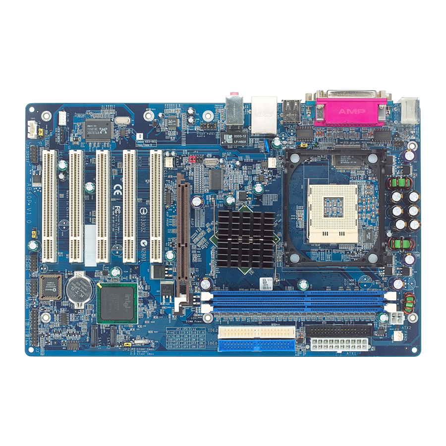
This section outlines how to install and configure your mainboard. Referring to the following mainboard layout helps you identify various jumpers, connectors, slots and ports. 3.1 Step-by-Step Installation Accessories Of AN51R nVIDIA nForce3 250 Chipset FAN1 Socket 754 Three DIMM Slots... -
Page 20: Step 1 Install The Cpu
Step 1 Install the CPU 1. Locate the CPU ZIF (Zero Insertion Force) socket on the upper-right sector of your mainboard (between the back panel connectors and the DIMM memory slots). 2. Pull the CPU ZIF socket lever slightly sideways away from the socket to unlock the lever, and then bring it to an upwardly vertical position. -
Page 21: Step 2 Set Jumpers
Step 2 Set Jumpers The default jumper settings have been set for the common usage standard of this mainboard. Therefore, you need not to reset the jumpers unless you re- quire special adjustments as the following case: Clear CMOS Setting For first-time DIY system builders, we recommend that you not change the default jumper settings if you are not quite familiar with the mainboard con- figuration procedures. -
Page 22: Step 4 Install Internal Peripherals In System Case
Step 4 Install Internal Peripherals in System Case Before you place the mainboard into your system case, we recommend that you first assemble all the internal peripheral devices into the computer hous- ing, including, but not limited to, the hard disk drive (IDE/HDD), floppy disk drive (FDD), CD-ROM drive, and ATX power supply unit. -
Page 23: Step 5 Mount The Mainboard On The Computer Chassis
Step 5 Mount the Mainboard on the Computer Chassis 1. You may find there are a lot of mounting holes on your computer chassis and mainboard. To match the holes on both properly, the key point is to make the back panel of the mainboard in a close fit with your system case, as shown below. -
Page 24: Step 6 Connect Front Panel Leds/Switches/Speaker/Usbs
Step 6 Connect Front Panel LEDs/Switches/Speaker/USBs You can find there are several cables existing in the system case and originat- ing from the front panel devices (HDD LED, Green LED, Reset switch, PC Speaker and USB devices etc.). These cables serve to connect the front-panel LEDs, switches, speaker and USB connectors to the mainboard's front-panel connectors group, as shown below. -
Page 25: Step 7 Connect Ide ,Floppy Disk Drives
Step 7 Connect IDE and Floppy Disk Drives 1. IDE cable connectors 2. Floppy cable connector 3.Serial ATA Connectors (SATA #1~4) SATA3 SATA4 SATA2 SATA1 - 18 -... -
Page 26: Step 8 Connect Other Internal Peripherals
Step 8 Connect Other Internal Peripherals 1. IR header (JP8) 2. Audio CD_IN connectors (CN4/CN5); Audio AUX_IN connector (CN6) AUX_IN CD_IN CD_IN 3. 1394 header (JP15) 1394 - 19 -... -
Page 27: Step 9 Connect The Power Supplies
4. Front Panel Audio Header (JP11) JP11 Front Audio Step 9 Connect the Power Supplies ATX1 1. System power connectors (ATX1/CN8) Step 10 Install Add-On Cards in Expansion Slots 1. Accelerated Grapics Port (AGP) Card 2. PCI Card - 20 -... -
Page 28: Step 11 Connect External Peripherals To Back Panel
Step 11 Connect External Peripherals to Back Panel You are now ready to connect the external peripherals to your system's back panel. 1. PS/2 Mouse Port 2. PS/2 Keyboard Port 3. LPT1 Port 4. COM1 Port 5. Clear CMOS Button 6. -
Page 29: Step 12 System Boot Up For The First-Time
Step 12 System Boot Up For the First-Time To ensure your system completedly and correctly installed, please refer to the above installation steps once again before first booting up your system. 1. Insert a system-bootable floppy disk (DOS 6.2X, Windows 9X/NT, or others), which contains the FDISK and FORMAT utilities. -
Page 30: Step 13 Install Drivers & Software Components
2000/ME/NT/XP operating systems. Make sure your operating system is already installed before running the installation programs on CD-ROM. 1. Insert the AN51R bundled CD-ROM into your CD-ROM drive. The auto- run program will display the main installation window on screen. -
Page 31: Jumper Settings
3.2 Jumper Settings Several hardware settings are made through the use of mini jumpers to con- nect jumper pins on the mainboard. Pin #1 could be located at any corner of jumpers, and the corner with a white right angle stands for Pin #1. There are several types of Pin #1 as shown below: 3-pin and multi-pin (>3) jumpers shown as follows: Pin #1 to the left:... - Page 32 Jumpers & Connectors Guide Refer to the mainboard layout on page 12 and this section to help you iden- tify jumpers, slots, and connectors along with their assigned functions. E9/E10 CPU/Memory/Expansion Slots Socket 754 : CPU socket for AMD Athlon 64 , 754-pins processor.
-
Page 33: Jumpers & Connectors Guide
Jumpers JP18 : Clear CMOS setting JP21 : Giga LAN setting JP22 : 1394 setting Back Panel Connectors : PS/2 mouse port : PS/2 keyboard port LPT 1 : Parallel port COM1 : Serial port Clear CMOS : Clear CMOS button SPDIF-In : SPDIF-In port 1394... - Page 34 Other Connectors ATX1/CN8 : ATX power supply connectors FAN1 : CPU fan connector FAN2/FAN3 : System fan connectors : IR header CN4/CN5 : Audio CD_IN connectors : Audio AUX_IN connector JP7/JP20 : Extended USB header JP11 : Front-Panel Audio header JP15 : 1394 header : PWRON button...
-
Page 35: Clear Cmos Setting (Jp18)
Jumpers Clear CMOS Setting (JP18) JP18 is used to clear CMOS data. Clearing CMOS will result in permanently erasing previous system configuration settings and the original factory-set system settings. Pin 1-2 (Default) Pin 2-3 (Clear CMOS) JP18 Step 1. Turn off the system power (PC-->Off). Step 2. -
Page 36: Giga Lan Setting (Jp21)
Giga LAN Setting (JP21) JP21 is used to set Giga LAN. Pin 1-2 Enable (Default) JP21 Pin 2-3 Disable 1394 Setting (JP22) JP22 is used to set 1394. Pin 1-2 Enable (Default) JP22 Pin 2-3 Disable - 29 -... -
Page 37: Back Panel Connectors Ps/2 Mouse & Ps/2 Keyboard Port Connectors
Back Panel Connectors PS/2 Mouse & PS/2 Keyboard Port Connectors Two 6-pin female PS/2 Mouse & Keyboard connectors are located on the rear panel of PS2 Mouse Port the mainboard. In a desktop computer, the PS/2 Mouse connector is situated on the top of the PS/2 Keyboard connector. -
Page 38: Ieee 1394 Connector
IEEE 1394 Port Connector IEEE 1394 Port This mainboard offers one 1394 port on back-panel. Plug device jack into an avail- able 1394 connector. USB Port Connectors This mainboard offers 4 USB ports on back panel. Plug each USB device jack into an available USB0~USB3 connector. -
Page 39: Line-In Port Connector
Line-In Port Connector Line-In Port B 1 1 Line-In is a stereo line-level input port that accepts a 1/8-inch TRS stereo plug. It can be used as a source for digital sound re- cording, and a source to be mixed with the output, or both. -
Page 40: Front Panel Connectors Hdd Led Connector (Hled)
Front Panel Connectors HDD LED Connector (HLED) Attach a connector cable from the IDE device LED to the 2-pin (HLED) header. The HDD LED lights up whenever an IDE device is active. Pin Assignments: 1= HDD LED+ 3= HDD LED- JP 19 GLED PLED... -
Page 41: Hardware Reset Connector (Rst)
Hardware Reset Connector (RST) Attach a cable to the 2-pin (RST) header. Pressing the reset switch causes the system to restart. Pin Assignments: 5= Reset button 7= Ground JP 19 GLED PLED PWON EPMI HLED SPEAKER ATX Power On/Off Switch Connector (PWON) The Power On/Off Switch is a momentary type switch used for turning on or off the ATX power supply. -
Page 42: Epmi Connector (Epmi)
EPMI Connector (EPMI) A Hardware System Management Interface (EPMI) header may be attached to a 2-pin momentary switch. Press the switch to force the system into a power sav- ing mode; press it again to resume it to a normal operation situation. Pin Assignments: 11= EXT-SMI JP 19... -
Page 43: Internal Peripheral Connectors
Internal Peripherals Connectors Enhanced IDE, Floppy Connectors The mainboard features two 40-pin dual-channel IDE device connectors (IDE1/IDE2) providing support for up to four IDE devices, such as CD-ROM and Hard Disk Drives (H.D.D.). This mainboard also includes one 34-pin floppy disk controller (FDC) to accommodate the Floppy Disk Drive (FDD). -
Page 44: Other Connectors Atx Power Supply Connectors (Atx1/Cn8)
Other Connectors ATX Power Supply Connectors (ATX1/CN8) This motherboard uses 20-pin ATX power header (ATX1), and comes with the other one header (CN8). Please make sure you plug each in the right direction. It is essential to have these two power supply connectors plugged or your system won't boot up. -
Page 45: Cpu And System Fan Connectors (Fan1/2/3)
CPU and System Fan Connectors (FAN1/2/3) The mainboard provides three onboard 12V cooling fan power connectors to support the CPU (FAN1) and the system (FAN2 / FAN3) cooling fans. +12V SENSE FAN1 FAN3 Note: Both cable wiring and type of plug may vary, which depend on the fan maker. -
Page 46: Audio Cd_In Connectors (Cn4/Cn5)
Audio CD_IN Connectors (CN4/CN5) Ports CN4 (Black)/CN5 (White) can be used to connect stereo audio inputs from CD-ROM, TV-tuner or MPEG card. CN 4 Pin Assignments: 1=CD In-Left 2=Ground CD_IN 3=Ground 4=CD IN-Right CN 5 CD_IN Pin Assignments: 1=Ground 2=CD-IN-Right 3=Ground 4=CD In-Left Audio AUX_IN Connector (CN6) -
Page 47: Extended Usb Headers (Jp7/Jp20)
Extended USB Headers (JP7/JP20) Headers JP7/JP20 (USB 5&6 and 7&8) are used to connect cables to USB connectors mounted on front panel or back panel. The USB cable is optional at the time of purchase. 2 4 6 8 10 JP 7 1 3 5 7 9 Pin Assignments:... -
Page 48: Ieee1394 Connector (Jp15)
IEEE1394 Connector (JP15) The header are used to connect the cable attached to 1394 connector which are mounted on front panel or back panel. But the 1394 cable is optional at the time of purchase. JP 15 8 10 Pin Assignments: 1=TPA+ 2=TPA- 3=GND... -
Page 49: System Memory Configuration
3.3 System Memory Configuration The AN51R mainboard has three 184-pin DIMM slots that allow you to install from 64MB up to 3GB of system memory. Each 184-pin DIMM (Dual In-line Memory Module) slot can accommdate 64MB, 128MB, 256MB, 512MB, and 1GB compliant 2.5V/2.6V single or double side 64-bit wide data path with or without ECC DDR-SDRAM modules. -
Page 50: Upgrade Memory
No.of dimms DIMM1 DIMM2 DIMM3 SPEED x8 single rank or x16 x8 single rank or x16 x8 single rank or x16 DDR 333 x8 single rank or x16 x8 single rank or x16 x8 duoble rank DDR 200 x8 single rank or x16 x8 duoble rank x8 single rank or x16 DDR 200... -
Page 51: Software Utility
Driver. F Install Utility - Installing Acrobat Reader and Winflash Utility. F Manual - Installing Acrobat Reader and AN51R user's manual in PDF format. F Link to Shuttle Homepage - Link to shuttle website homepage. F Browse this CD - Allows you to see contents of this CD. -
Page 52: A Install Directx9 Utility Driver
4.2.A Install DirectX9 Utility Driver Select using your pointing device (e.g. mouse) on the "Install DirectX9 Utility Driver" bar to install DirectX9 Utility driver. Once you made your se- lection, a Setup window run the installation automatically. When the copying files is done, make sure you reboot the system to take the installation... -
Page 53: C Install Broadcom Giga Lan Driver
4.2.C Install Broadcom Giga LAN Driver Select using your pointing device (e.g. mouse) on the " Install Broadcom Giga LAN Driver" bar to install LAN driver . Once you made your se- lection, a Setup window run the installation automatically. When the copying files is done, make sure you reboot the system to... -
Page 54: A View The User's Manual
If the AutoRun screen does not appear, double click on AutoRun icon in My Computer to bring up Shuttle Mainboard Software Setup screen. Select using your pointing device (e.g. mouse) on the "AN51R Manual" bar. Then Online Infor- mation windows will appear on your screen. -
Page 55: Bios Setup
5 BIOS SETUP AN51R BIOS ROM has a built-in Setup program that allows users to modify the basic system configuration. This information is stored in battery-backed RAM so that it retains the Setup information even if the system power is turned off. -
Page 56: The Main Menu
5.2 The Main Menu Once you enter the Award BIOS(tm) CMOS Setup Utility, the Main Menu will appear on the screen. The Main Menu allows you to select from several setup functions and two exit choices. Use the arrow keys to select among the items and press <Enter>... - Page 57 PnP/PCI Configurations This option configures how PnP (Plug and Play ) and PCI expansion cards operate in your system. PC Health Status This entry shows the current system temperature, voltage, and fan speed. Ratio/Voltage Control Use this menu to specify your settings for the ratio/voltage control. Load Fail-Safe Defaults Use this menu to install fail-safe defaults for all appropriate items in the setup utility.
-
Page 58: Standard Cmos Features
Standard CMOS Features Use the arrow keys to highlight the item and then use the <PgUp> or <PgDn> keys to select the value you want in each item. Date (mm : dd : yy) Set the system date. Note that if you are running a Windows OS, this items are automatically updated whenever you make changes to the Windows Date. - Page 59 Base Memory/Extended Memory/Total Memory These items are automatically detected by the system at start up time. These are display-only fields. You can't make change to these fields. ****************************************************** IDE Adapters The IDE adapters control the hard disk drive. Use a separate sub-menu to configure each hard disk drive.
-
Page 60: Advanced Bios Features
Advanced BIOS Features This section allows you to configure your system for basic operation. Hot Disk Boot Priority This item let you select hot disk boot priority. Ø The choice: Pri.Master/Slave, Sec.Master/Slave, USB HDD 0~2, Bootable Add-in Cards. BIOS Write Protect This item let you enable or disable the BIOS Write Protect. - Page 61 Ø The choice: Enabled or Disabled. Quick Power On Self Test Enable this item to shorten the power on testing (POST) and have your system start up faster. You might like to this item after you are confident that your system hardware is operating smoothly. Ø...
- Page 62 Typematic Rate (Chars/Sec) This item sets how many times the keystroke will be repeated in a second when you hold a key down. Ø The choice: 6, 8, 10, 12, 15, 20, 24, or 30. Typematic Delay (Msec) Sets the delay time after a key is held down. Ø...
-
Page 63: Advanced Chipset Features
Advanced Chipset Features This section allows you to configure the system based on the specific features of the installed chipset. This chipset manages bus speeds and access to system memory resources, such as DRAM and the external cache. It also coordinates communications between the conventional PCI bus. - Page 64 Min RAS# active time (tRAS) The item defines the numbers of cycles for RAS to be allowed to precharge. Ø The choice: Auto, 5~15 Bus Clocks. Row precharge Time (tRP) If an insufficient number of cycles is allowed for the RAS to accumulate its charge before DRAM refresh, the refresh may be-incompleted, and the DRAM may fail to retain data.
- Page 65 Clock Spread Spectrum This item allows you to set the Clock spread spectrum modulation. Ø The choice: Enabled or Disabled. HT Frequency This item allows you to set the HT Frequency. Ø The choice: 1X, 2X, 3X, 4X or 5X. Special I/O for PCI Card This item enable/disable the Special I/O for PCI Card.
-
Page 66: Integrated Peripherals
Integrated Peripherals Onboard IDE Device Press <Enter> to enter the sub-menu of detailed options. Raid Function Setup Press <Enter> to enter the sub-menu of detailed options. IDE RAID, IDE Channel 0/1 Master/Slave RAID or SATA/ SATA-2 Primary/Secondary Master RAID. The item allows you to set raid function. Ø... - Page 67 IDE Prefetch Mode The onboard IDE drive interface support IDE prefetching for faster drive access. If you install a primary and/or secondary add-on IDE interface, set this field to Disabled if the interface does not support prefetching. Ø The Choice: Enabled or Disabled. Serial-ATA (External PHY) This item allows you to enable or disable Serial-ATA (External PHY).
- Page 68 Broadcom Gb/FE LAN ROM This item allows you to enable or disable the the Gb/FE LAN ROM. Ø The Choice: Enabled or Disabled. Onboard Super I/O Device Press <Enter> to enter the sub-menu of detailed options. Onboard FDC Controller This item specifices onboard floppy disk drive controller. This setting allows you to connect your floppy disk drives to the onboard floppy connector.
-
Page 69: Power Management Setup
Power Management Setup The Power Management Setup allows you to configure your system to most effectively saving energy while operating in a manner consistent with your own style of computer use. ACPI Function This item defines the ACPI (Advanced Configuration and Power Man- agement) feature that makes hardware status information available to the operating system, enables a PC to turn its peripherals on or off for improving the power management, and allows a PC turned on or off by... - Page 70 HDD Power Down The IDE hard drive will spin down if it is not accessed within a specified length of time. Options are from 1 Min to 15 Min and Disabled. Ø The choice: Disabled or 1 Min~15 Min. HDD Down In Suspend The item allows you to enable or disable the HDD Down In Suspend.
-
Page 71: Pnp/Pci Configurations
PS2 Keyboard Power ON Set a key to awaken the system from a PS2 keyboard. Ø The choice: Password, Hot KEY or Disabled. KB Power ON Password Press <Enter> to set a password to awaken the system from a key- board. -
Page 72: Pc Health Status
PC Health Status The following items provide you with information about the system's current operating status. You cannot make changes to one of them. CPU Voltage AGP Voltage 3.3V VIN +5V VIN +12V VIN -12V VIN RAM Voltage 5V SBVIN Voltage Battery System Temperature CPU Temperature... -
Page 73: Load Fail-Safe Defaults
Load Fail-Safe Defaults When you press <Enter> on this item, you will get a confirmation dialog box with a message similar to: Load Fail-Safe Defaults (Y/N) ? N Pressing 'Y' loads the BIOS default values for the most stable, minimal performance system operations. -
Page 74: Save & Exit Setup
New Password Setting: 1. While pressing <Enter> to set a password, a dialog box appears to ask you enter a password. 2. Key in a new password. The password can not exceed eight charac- ters. 3. System will request you to confirm the new password again. 4. -
Page 75: Appendix A. Update Memory Configurations
Appendix A. Update Memory Configurations: Unbuffered DIMM Support No.of dimms DIMM 1 DIMM 2 DIMM 3 Max Speed 1T Max Speed 2T DDR 400 DDR 400 DDR 400 DDR 400 DDR 400 DDR 400 DDR 400 DDR 400 DDR 400 DDR 400 DDR 400 DDR 400...
Need help?
Do you have a question about the AN51R and is the answer not in the manual?
Questions and answers