Advertisement
Available languages
Available languages
Quick Links
Quick Start Guide
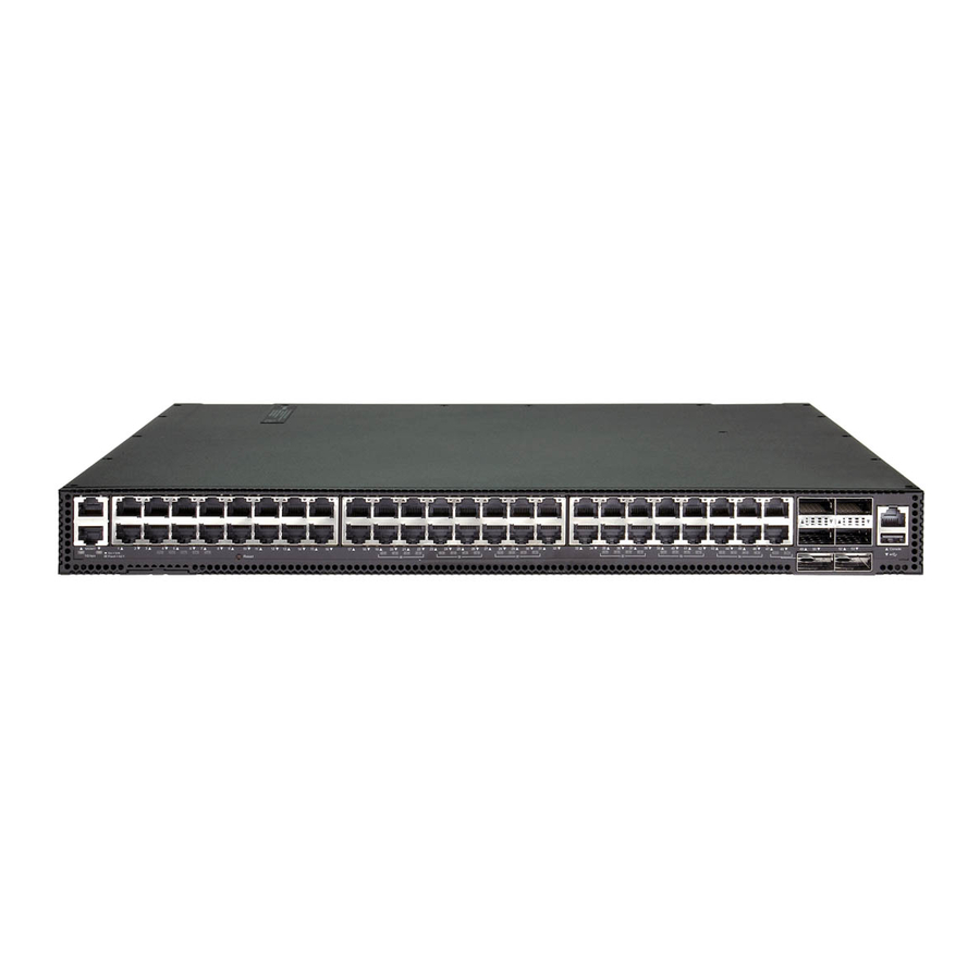
54-Port 10G/100G Ethernet Switch
AS5835-54T
1.
54-Port 10G/100G Ethernet Switch AS5835-54T
2.
Rack mounting kit—2 front-post brackets, 2 rear-post
brackets, 20 screws, and 2 ear-locking screws
3.
Power cord (included with AC PSUs only)
4.
Ground wire (included with DC PSUs only)
Warning:
For a safe and reliable installation, use only
the accessories and screws provided with the AS5835-
54T. Use of other accessories and screws could result in
damage to the unit. Any damages incurred by using
unapproved accessories are not covered by the warranty.
Avertissement:
Pour une installation sûre et fiable,
utilisez uniquement les accessoires et les vis fournies avec
le AS5835-54T. L'utilisation d'autres accessoires et vis
pourrait endommager l'appareil. Les dommages causés
par l'utilisation d'accessoires non approuvés ne sont pas
couverts par la garantie.
Caution:
The switch includes plug-in power supply (PSU)
and fan tray modules that are installed into its chassis. All
installed modules must have a matching airflow direction.
That is, if the installed power modules have a front-to-back
(F2B) airflow direction, all the installed fan tray modules
must also have a F2B airflow direction.
Attention:
Le commutateur comprend des modules
d'alimentation et de bac de ventilateurs installés sur son
châssis. Tous les modules installés doivent avoir une
direction de circulation d'air correspondante. C'est-à-dire
que tous les modules doivent avoir la même direction de
circulation d'air : avant vers arrière (F2B), ou arrière vers
avant (B2F).
Note:
The switch has the Open Network Install
Environment (ONIE) software installer pre-loaded on the
switch, but no switch software image. Information about
compatible switch software can be found at
www.edge-core.com.
1
Attach the Brackets
2
1.
Attach each of the front- and rear-post brackets to the switch
using four of the included bracket screws.
2.
Use the screws and cage/clip nuts supplied with the rack to
secure the switch in the rack.
www.edge-core.com
Package Contents
1
2
1
1
3
4
5.
Console cable—RJ-45 to D-Sub
6.
DC power connector (included with 48 VDC PSU only)
7.
Documentation—Quick Start Guide (this document) and
Safety and Regulatory Information
Caution:
Installing the switch in a rack requires two
people. One person should position the switch in the rack,
while the other person secures it using the rack screws.
Attention:
Deux personnes sont nécessaires pour installer
un commutateur dans un bâti : La première personne va
positionner le commutateur dans le bâti, la seconde va le
fixer avec des vis de montage.
2
Adjust Rear-Post Bracket Ears
1.
Lock the position of the rear-post bracket ears using the included
position-locking screws.
You can adjust the rear-post bracket ears to fit different rack
depths from 56 cm to 75 cm.
3
Ground the Switch
1
2
1.
Ensure the rack is properly grounded and in compliance with
ETSI ETS 300 253. Verify that there is a good electrical
connection to the grounding point on the rack (no paint or
isolating surface treatment).
2.
Attach the grounding wire (#14 AWG) to the grounding point
on the switch rear panel. Then connect the other end of the wire
to rack ground.
– 1 –
5
6
1
E092019-CS-R01
150200002099A
7
Advertisement

Subscribe to Our Youtube Channel
Related Manuals for Edge-Core AS5835-54T


Summary of Contents for Edge-Core AS5835-54T
- Page 1 Pour une installation sûre et fiable, utilisez uniquement les accessoires et les vis fournies avec fixer avec des vis de montage. le AS5835-54T. L’utilisation d’autres accessoires et vis pourrait endommager l’appareil. Les dommages causés par l’utilisation d’accessoires non approuvés ne sont pas Adjust Rear-Post Bracket Ears couverts par la garantie.
-
Page 2: Connect Power
Quick Start Guide Perform Initial System Boot Caution: The earth connection must not be removed unless all supply connections have been disconnected. If the network operating system (NOS) installer is located on a Attention: Le raccordement à la terre ne doit pas être retiré network server, first connect the RJ-45 Management (Mgmt) port sauf si toutes les connexions d’alimentation ont été... -
Page 3: Hardware Specifications
Quick Start Guide Hardware Specifications Regulatory Compliances Switch Chassis Emissions EN 55032:2015+AC:2016, Class A Size (WxDxH) 442.5 x 473.3 x 43.95 mm (17.42 x 18.63 x 1.73 in) EN 61000-3-2:2014, Class A EN 61000-3-3:2013 Weight 9.59 kg (21.14 lb), with two installed PSUs FCC Class A VCCI Class A Temperature... - Page 4 快速入门指南 54 端口 10G/100G 以太网交换机 AS5835-54T 包装清单 54 端口 10G/100G 以太网交换机 AS5835-54T 接地线 (仅随直流电源附带) 控制台线缆 —RJ-45 转 D-Sub 机架安装套件 — 2 个前柱支架, 2 个后柱支架, 20 个螺丝 和 2 个吊耳螺丝。 DC 电源转接头 (仅随 48 VDC 电源附带) 电源线 (仅随交流电源附带) 快速入门指南 安全和管制信息 文档 —...
- Page 5 快速入门指南 连接电源 执行初次系统启动 如果网络操作系统 (NOS) 安装程序位于网络服务器中,应首 先使用 100 欧姆的 5、 5e 类或以上双绞线将 RJ-45 管理 (Mgmt) 端口连接到网络。 (NOS 安装程序位于相连的存储装 置中时不需要。 ) 启动交换机。等待 ONIE 软件找到和执行 NOS 安装程序,然 后等待安装程序加载 NOS 软件映像。 以后交换机启动时将跳过 ONIE 而直接运行 NOS 软件。 注意: 请参考网络操作系统 (NOS) 安装程序和 NOS 文档 以详细了解软件选项和如何设置 ONIE。 将一个或两个...
- Page 6 快速入门指南 硬件规格 直流输入 -36 – -75 VDC, 14–7 A 交换机机箱 管制符合性 尺寸 (WxDxH) 442.5 x 473.3 x 43.95 mm (17.42 x 18.63 x 1.73 英 寸) 辐射 EN 55032:2015+AC:2016, Class A EN 61000-3-2:2014, Class A 重量 9.59 kg (21.14 磅) ,安装有两个 PSU EN 61000-3-3:2013 FCC Class A 温度...
- Page 7 快 速 入 門 指 南 54 埠 10G/100G 乙太網路交換器 AS5835-54T 包裝內容物 54 埠 10G/100G 乙太網路交換器 AS5835-54T 接地線 (僅 DC PSU 隨附) 機櫃安裝套件 —2 個前柱托架、2 個後柱托架、20 個螺絲 控制電纜 (Console Cable)- RJ45 轉 D-Sub 和 2 個固定片鎖定螺絲 DC 電源轉接頭 (僅 48 VDC PSU 隨附)...
- Page 8 快速入門指南 連接電源 執行初次系統啟動 若網路作業系統 (NOS)安裝程式位於網路伺服器,先使用 100-ohm 第 5 類、5e 類或更優之雙絞線電纜,連接 RJ-45 管 理 (Mgmt)埠至網路。 (若 NOS 安裝程式位於所附儲存設 備中,則不需要。) 啟動交換器。等待 ONIE 軟體找尋並執行 NOS 安裝程式,並 等待安裝程式載入 NOS 軟體映像檔。 之後交換器啟動時,會跳過 ONIE,直接運行 NOS 軟體。 備註: 有關 ONIE 軟體選項和設置的詳細資訊,請參閱 網路作業系統 (NOS)安裝程式和 NOS 文件。 在交換器中安裝 1 個或 2 個 AC 或 DC PSU。 連接網路線...
- Page 9 快速入門指南 硬體規格 DC 輸入 -36 – -75 VDC、14–7 A 交換器機箱 符合法規 尺寸(寬 x 深 442.5 x 473.3 x 43.95 mm(17.42 x 18.63 x 1.73 x 高) 吋) 排放 EN 55032:2015+AC:2016, Class A EN 61000-3-2:2014, Class A 重量 9.59 kg (21.14 lb) ,包含兩個安裝 PSU EN 61000-3-3:2013 FCC Class A 溫度...
Need help?
Do you have a question about the AS5835-54T and is the answer not in the manual?
Questions and answers