Edge-Core AS7712-32X Quick Start Manual
32-port 100g ethernet data center spine switch
Hide thumbs
Also See for AS7712-32X:
- Quick start manual (9 pages) ,
- Safety and regulatory information manual (6 pages)
Advertisement
Quick Links
Q ui c k Sta r t G u id e
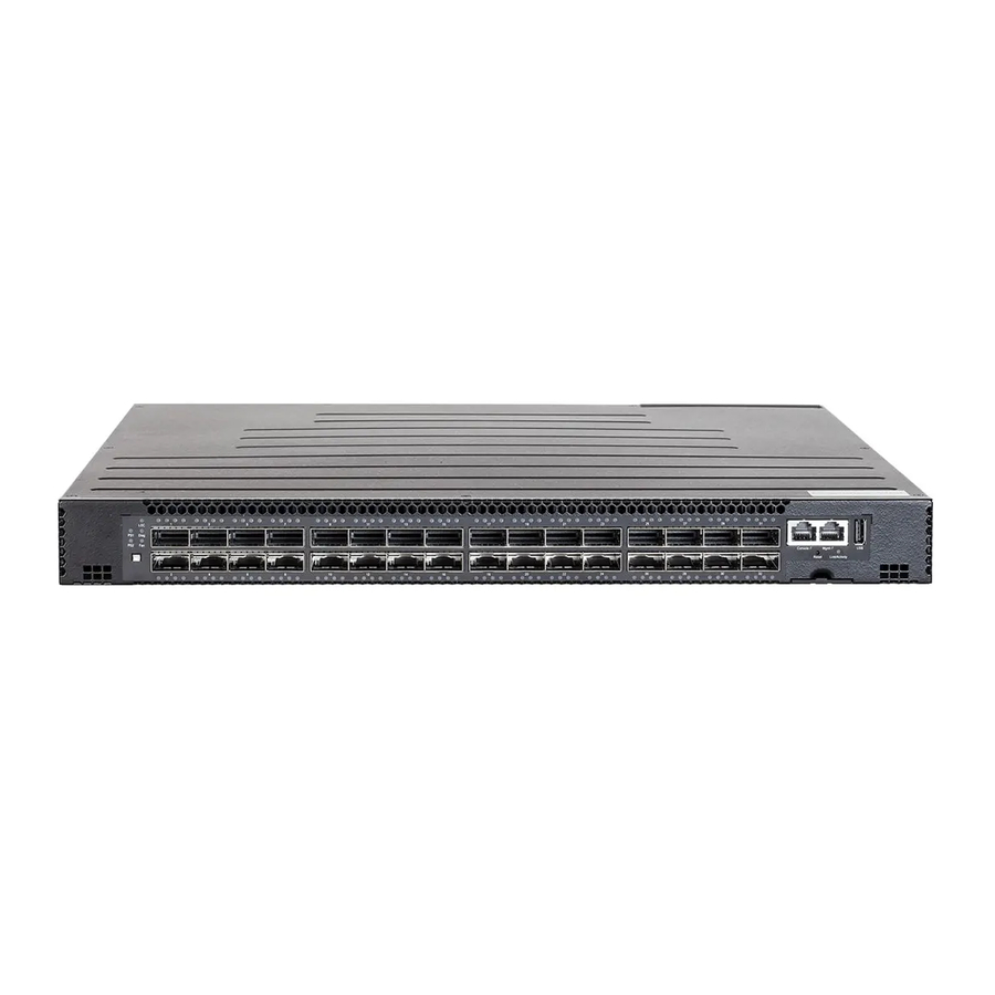
32-Port 100G Ethernet Data Center Spine Switch
AS7712-32X
1. Unpack the Switch and Check Contents
Rack Mounting Kit—2 front-post brackets, 2 rear-post
brackets, 20 screws, and 2 ear-locking screws
Power Cord—Japan, US, Continental Europe, or UK
Console Cable—RJ-45 to DB-9
Documentation—Quick Start Guide (this document)
and Safety and Regulatory Information
Note:
The switch has the Open Network Install
Environment (ONIE) software installer pre-loaded on the
switch, but no switch software image. Information about
compatible switch software can be found at
www.edge-core.com.
Caution:
The switch includes plug-in power supply (PSU)
and fan tray modules that are installed into its chassis. All
rear-installed modules must have a matching airflow
direction. That is, if the installed power modules have a
front-to-back (F2B) airflow direction, all the installed fan
tray modules must also have a F2B airflow direction.
The airflow direction of PSU and fan tray modules is
indicated by the color the release lever or handle on the
modules. Blue indicates an intake (cool) airflow, and red
indicates an exhaust (warm) airflow. Therefore, the fan tray
handles and PSU release levers must always be the same
color, either all blue or all red. The airflow direction of fan
tray modules is also indicated by labels on the modules.
2. Mount the Switch
1
3
1
Attach each of the front- and rear-post brackets to the
switch using four of the included bracket screws.
2
Use an additional two screws to secure each of the rear-post
brackets at the mid-point on the sides of the switch.
3
Use the screws and cage nuts supplied with the rack to
secure the switch in the rack.
www.edge-core.com
AS7712-32X
100G Data Center Switch
4
1
2
4
Lock the position of the rear-post bracket ears using the
included position-locking screws.
You can also adjust the rear-post bracket ears to fit different
rack depths from 56 cm to 85 cm.
Caution:
Installing the switch in a rack requires two
people. One person should position the switch in the rack,
while the other secures it using the rack screws.
装置の吸排気に必要な領域を マニ ュ アル上に規定 し て
い る 。
3. Ground the Switch
1
2
1
Ensure the rack is properly grounded and in compliance
with ETSI ETS 300 253. Verify that there is a good electrical
connection to the grounding point on the rack (no paint or
isolating surface treatment).
2
Attach a lug (not provided) to an 18 AWG minimum
grounding wire (not provided), and connect it to the
grounding point on the switch rear panel. Then connect the
other end of the wire to rack ground.
Caution:
The earth connection must not be removed
unless all supply connections have been disconnected.
4. Connect Power
2
1
Install one or two AC power modules in the switch.
The switch supports up to two PSUs that must have the
same matching airflow direction as the installed fan tray.
2
Connect an external AC power source to the modules.
– 1 –
1
E102015-CS-R01
150200001281A
Advertisement

Related Manuals for Edge-Core AS7712-32X


Summary of Contents for Edge-Core AS7712-32X
- Page 1 Q ui c k Sta r t G u id e 32-Port 100G Ethernet Data Center Spine Switch AS7712-32X Lock the position of the rear-post bracket ears using the 1. Unpack the Switch and Check Contents included position-locking screws. You can also adjust the rear-post bracket ears to fit different rack depths from 56 cm to 85 cm.
- Page 2 Quick Start Guide 5. Verify Switch Operation 8. View the Product Label Verify basic switch operation by checking the system LEDs. When operating normally, the PS1/PS2, Diag, and Fan LEDs should all be on green. The switch product label is located below the Console and Management ports on the right side of the front panel.
Need help?
Do you have a question about the AS7712-32X and is the answer not in the manual?
Questions and answers