Table of Contents
Advertisement
Quick Links
Quick Start Guide
48-Port Ethernet Switch
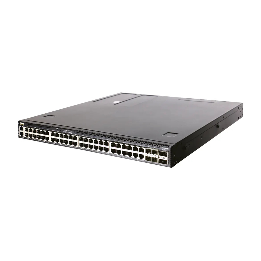
AS4630-54PE
1
1.
AS4630-54PE Ethernet Switch
2.
Rack mounting kit—2 brackets and 8 screws
3.
2 x Power cord
4
1
2
3
1.
1x USB port
2.
1 x Management port
3.
1 x Serial console port
4.
System buttons/LEDs
5.
48 x RJ45 1G PoE ports
System Buttons/LEDs
STK M/S button
Reset button
System LED: Green (OK), Amber (fault)
PRI LED: Green (primary unit), Amber (secondary unit)
PSU LEDs: Green (OK), Amber (fault)
STK LEDs: Green (stacking ports active)
FAN LED: Green (OK), Amber (fault)
PoE LED: Green (OK), Amber (High PoE load)
FRU Replacement
PSU Replacement
1.
Remove the power cord.
2.
Press the release latch and
remove the PSU.
3.
Install replacement PSU with
matching airflow direction.
*150200002243A_R01*
Package Contents
5
Fan Tray Replacement
1.
Loosen the fan tray screw.
2.
Remove fan tray from the
chassis.
3.
Install replacement fan with
matching airflow direction.
2
3
4.
Console cable—RJ-45 to D-Sub
5.
Documentation—Quick Start Guide (this document) and Safety
and Regulatory Information
Overview
8
7
6
6.
4 x SFP28 25G ports
7.
2 x QSFP28 40G/100G uplink or stacking ports
8.
3 x Fan trays
9.
2 x AC PSUs
RJ-45 Port LEDs: Green (link), Amber (link with PoE), Blinking (activity)
SFP28 Port LEDs: White (25G), Green (10G), Blinking (activity)
QSFP28 Port LEDs: White (100G), Green (40G link), Blinking (activity)
PSU Status LED: Green (OK), Red (fault or fan failure)
Fan Tray Status LED: Green (OK), Red (fault)
1. F2B Airflow
Remove front-to-back (F2B)
airflow fan trays (red handles) and
PSUs (red release latches).
– 1 –
www.edge-core.com
4
9
Port/FRU LEDs
Airflow Reversal
2. B2F Airflow
Install back-to-front (B2F) airflow
fan trays (blue handles) and PSUs
(blue release latches).
5
E072020-MR-R01
150200002243A
Advertisement
Table of Contents

Related Manuals for Edge-Core AS4630-54PE


Summary of Contents for Edge-Core AS4630-54PE
- Page 1 Quick Start Guide 48-Port Ethernet Switch www.edge-core.com AS4630-54PE Package Contents AS4630-54PE Ethernet Switch Console cable—RJ-45 to D-Sub Rack mounting kit—2 brackets and 8 screws Documentation—Quick Start Guide (this document) and Safety 2 x Power cord and Regulatory Information Overview 1x USB port...
-
Page 2: Installation
(ONIE) software installer preloaded on the switch, but no switch software image. Information about compatible switch software AC Power can be found at www.edge-core.com Install two AC PSUs and connect them to an AC power source. Mount the Switch Verify Switch Power Check the PSU LEDs The PSU1/PSU2 LEDs should be on green when operating normally. -
Page 3: Make Network Connections
Quick Start Guide 1. Edgecore Cumulus Linux software option Note: Stacking support is dependent on the switch software. To make basic switch configuration changes, connect a PC to For stacking support information, refer to the NOS software documentation. the switch's RJ-45 console port using the included console cable. 2. - Page 4 快速入門指南 48 埠⼄太網路交換器 AS4630-54PE 包裝內容物 AS4630-54PE ⼄太網路交換器 控制電纜 (Console Cable)− RJ45 轉 D-Sub 機櫃安裝套件 —2 個托架和 8 個螺絲 ⽂件−快速入門指南 (本⽂件)及安全及法規資訊 2 x 電源線 簡介 1x USB 連接埠 48x RJ45 1G PoE 連接埠 1x 管理連接埠 4x SFP28 25G 連接埠 1x 序列主控台連接埠...
- Page 5 (avant-arrière ou arrière-arrière). 說明: 裝置具有預載於交換器上的開放網路安裝環境 (ONIE) 軟體安裝程式,但沒有交換器軟體映像檔。關於相 容交換器軟體的資訊,可上此網站: www.edge-core.com。 AC 電源 安裝兩個 AC PSU 並將其連接至 AC 電源。 安裝交換器 確認交換器電源 檢查 PSU LEDs 正常操作時,PSU1 ∕ PSU2 LED 應亮綠燈。...
- Page 6 快速入門指南 1.Edgecore Cumulus Linux 軟體選項 備註: 堆疊支援視交換器軟體而定。閱於堆疊支援資訊, 請參閱 NOS 軟體⽂件。 若要進⾏基本的交換器配置變更,請使用隨附的 主控台纜線將電腦連接至交換器的 RJ-45 主控台連接埠。 2. 配置電腦的序列埠 硬體規格 115200 bps、8 個字元、無奇偶 (檢驗碼) 、1 個停止位元、8 個 交換器機箱 資料位元,並且無流量控制。使用預設設定值登入 Linux 介面:使 尺寸(寬 x 深 438 x 442 x 43.7 mm(17.24 x 17.40 x 1.72 英寸) x 高)...
- Page 7 AS4630-54PE AS4630-54PE —RJ-45 D-Sub —2 — 1x USB 4x SFP28 25G 2x QSFP28 40G/100G /LED 48x RJ45 1G PoE /LED /FRU LED STK M/S RJ-45 PoE) SFP28 (25G) (10G) PRI LED QSFP28 (100G) (40G) PSU LED STK LED PoE LED 1.F2B...
- Page 8 Attention: Le appareil comprend des modules d’alimentation et de modules de ventilation installés dans son châssis.Assurez- vous que tous les modules installés ont une direction d’air adaptée (avant-arrière ou arrière-arrière). (ONIE) www.edge-core.com 次 PSU LED PSU1/PSU2 LED 1.ONIE (NOS) 动...
- Page 9 1.Edgecore Cumulus Linux 等 境 等 RJ-45 次 115200 bps Linux “cumulus” “CumulusLinux!” 438 x 442 x 43.7 mm 17.24 x 17.40 x 1.72 Cumulus 7.67 kg (16.91 lb) https://docs.cumulusnetworks.com/ 0° C 45° C 32° F 113° F -40° C 70°...
Need help?
Do you have a question about the AS4630-54PE and is the answer not in the manual?
Questions and answers