Table of Contents
Advertisement
Quick Links
Advertisement
Table of Contents

Related Manuals for BLAUBERG Iso-Mix 150


Summary of Contents for BLAUBERG Iso-Mix 150
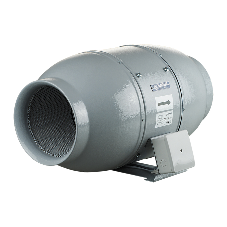
- Page 1 INLINE FANS IN SOUND-INSULATED CASING Iso-Mix USER’S MANUAL...
-
Page 2: Table Of Contents
CONTENTS Safety requirements ............................................3 Delivery set ................................................9 Operation guidelines ............................................9 Brief description ..............................................9 Product sales ................................................. 9 Designation key ..............................................11 Installation and set-up............................................. 12 Connection to power mains ........................................18 Electronics operation algorithm ....................................... 23 Technical maintenance ........................................... -
Page 3: Safety Requirements
SAFETY REQUIREMENTS All user’s manual requirements as well as the provisions of all the applicable local and national construction, electrical, and technical norms and standards must be observed when installing and operating the unit. Disconnect the unit from power supply prior to any connection, servicing, maintenance, and repair operations. - Page 4 • Misuse of the unit and any unauthorized modifications are not allowed. • Do not expose the device to adverse atmospheric agents (rain, sun, etc.). • Transported air must not contain any dust or other solid impurities, sticky substances, or fibrous materials. •...
- Page 5 • No part of this publication may be reproduced, stored in a retrieval system, or transmitted, in any form or by any means in any information search system or translated into any language in any form without the prior written permission of the Company. WARNING! Similar to the use of any other household electrical appliances when operating this fan, the following basic rules must be followed:...
- Page 6 The connection to the supply mains must be made through a means of disconnection, which is incorporated in the fixed wiring in accordance with the wiring rules, and has a contact separation in all poles that allows for full disconnection under overvoltage category III conditions.
- Page 7 Ensure that the appliance is switched off from the supply mains before removing the guard. WARNING: If unusual oscillating movements is observed, immediately stop using the appliance and contact the manufacturer, its service agent or suitably qualified persons. The replacement of parts of the safety suspension system device shall be performed by the manufacturer, its service agent or suitably qualified persons.
- Page 8 Fixing means for attachment to the ceiling such as hooks or other devices shall be fixed with a sufficient strength to withstand 4 times the weight of the appliance. The mounting of the suspension system shall be performed by the manufacturer, its service agent or suitably qualified persons.
-
Page 9: Delivery Set
DELIVERY SET 1 pc. Screws with dowels 4 pcs. Plastic screwdriver (only for the models with a timer) 1 pc. User’s manual 1 pc. Packing box 1 pc. OPERATION GUIDELINES The fan is rated for connection to single-phase AC 220-240 V/50 Hz or 220 V/60 Hz power mains. The unit is rated for continuous operation. - Page 10 Overall dimensions: Ø D Iso-Mix 100 Iso-Mix 125 Iso-Mix 150 Iso-Mix 160 Iso-Mix 200 Iso-Mix 250 Iso-Mix 315 øD H øD H...
-
Page 11: Designation Key
DESIGNATION KEY Iso-Mix 100 T 120 V/60 Hz Unit voltage: _ — 220-240 V 50/60 Hz (default); YYY V/ZZ Hz — mains parameters other than the default ones Options: T: timer US: speed switch FR1: integrated speed controller from 0 to 100 %, power cord with a mains plug G1: speed controller with an electronic thermostat and external temperature sensor. -
Page 12: Installation And Set-Up
INSTALLATION AND SET-UP The fan is suitable both for horizontal or vertical mounting on the floor, on the wall or on the ceiling. While mounting the fan, provide extra protection against water ingress, such as: • For the top mounting install an outer protecting hood above. •... - Page 13 Cut off power supply and make sure electricity Lead the power cable to the ventilation hole, drill the has been turned off. Mark the holes for fixing the mounting holes and install the dowels. fan and the power cable. For any mounting position connect an air duct on both Fix the fan with the screws.
- Page 14 Cut off power supply and make sure electricity has been turned off. Remove the cover of the fan. Connect the power cord wires to the terminal block and Supply power to the fan. assemble the fan in reverse order.
- Page 15 Mounting sequence for different fan models...
- Page 17 Iso-Mix ... T Iso-Mix ... US 2 min 30 min STOP Iso-Mix ... G1 (GI1, GT1, GTI1, GS1, GSI1) Iso-Mix ... W Thermostat control knob Speed Speed control knob control knob...
-
Page 18: Connection To Power Mains
CONNECTION TO POWER MAINS The fan is rated for connection to single-phase AC 220-240 V/50 (60) Hz power mains. TERMINAL DESIGNATIONS ON WIRING DIAGRAMS L1 — minimum speed terminal S — external speed controller L2 — maximum speed terminal ST — external switch QF —... - Page 19 Iso-Mix 100/125 Max/min...
- Page 20 Iso-Mix 150/160/200/250/315 Max/min...
- Page 21 Iso-Mix ... T terminal block for 4 contacts terminal block for 5 contacts Max/min terminal block for 5 contacts terminal block for 4 contacts...
- Page 22 terminal block for 5 contacts terminal block for 4 contacts...
-
Page 23: Electronics Operation Algorithm
ELECTRONICS OPERATION ALGORITHM It is possible to control the fan rotation speed without options by voltage, as well as by thyristor controllers. The speed controller is purchased separately. Warning! When adjusting the voltage, make sure there is no unusual noise or vibration at reduced motor speed. The motor current may exceed the rated current during voltage regulation. - Page 24 The terminal compartment incorporates 2 control knobs: • presetting the speed • setting the threshold for the electronic thermostat The thermostat operation indicator is located on the fan cover. It lights up when the air temperature exceeds the set value. To set the thermostat threshold, turn the temperature knob clockwise to increase the value and counter-clockwise to decrease the value.
-
Page 25: Technical Maintenance
TECHNICAL MAINTENANCE The fan maintenance periodicity is at least once per 6 months. Maintenance steps: Disconnect the fan from power supply and make sure Clean the fan with a soft dry cloth or a brush. electricity has been turned off. Disconnect an air duct on both sides of the fan. -
Page 26: Troubleshooting
TROUBLESHOOTING Problem Possible reasons Troubleshooting Make sure the power supply line No power supply. is connected correctly, otherwise When the unit is connected to power mains, the fan does not rotate and troubleshoot the connection error. does not respond to any controls. Internal connection fault. -
Page 27: Manufacturer's Warranty
Our ventilation products also come with a twoe year limited warranty given by Blauberg Australasia Pty Ltd, with an office at Unit 5, 45A Eastern Creek Drive, Eastern Creek, New South Wales 2766, as set out in the instruction manual in the box. - Page 28 FOLLOWING THE REGULATIONS STIPULATED HEREIN WILL ENSURE A LONG AND TROUBLE-FREE OPERATION OF THE UNIT. USER’S WARRANTY CLAIMS SHALL BE SUBJECT TO REVIEW ONLY UPON PRESENTATION OF THE UNIT, THE PAYMENT DOCUMENT AND THE USER’S MANUAL WITH THE PURCHASE DATE STAMP.
- Page 31 Quality Inspector’s Stamp Sold by (name and stamp of the seller) Manufacture Date Purchase Date...
- Page 32 Iso-Mix 120 V/60 Hz GTI1 GSI1 www.blaubergventilation.com.au Blauberg_Australasia_97EN-05...
Need help?
Do you have a question about the Iso-Mix 150 and is the answer not in the manual?
Questions and answers