Table of Contents
Advertisement
Quick Links
Advertisement
Table of Contents

Related Manuals for BLAUBERG Iso-Mix


Summary of Contents for BLAUBERG Iso-Mix
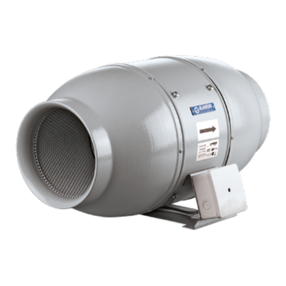
- Page 1 INLINE FANS IN SOUND-INSULATED CASING Iso-Mix USER’S MANUAL...
-
Page 2: Table Of Contents
Manufacturer’s warranty ..........................................26 This user’s manual is a main operating document intended for technical, maintenance, and operating staff. The manual contains information about purpose, technical details, operating principle, design, and installation of the Iso-Mix unit and all its modifications. -
Page 3: Safety Requirements
SAFETY REQUIREMENTS This unit is not intended for use by persons (including children) with reduced physical, sensory or mental capabilities, or lack of experience and knowledge, unless they have been given supervision or instruction concerning use of the unit by a person responsible for their safety. - Page 4 Connection to the mains must be made through a disconnecting device, which is integrated into the fixed wiring system in accordance with the wiring rules for design of electrical units, and has a contact separation in all poles that allows for full disconnection under overvoltage category III conditions.
- Page 5 The replacement of parts of the safety suspension system device shall be performed by the manufacturer, its service agent or suitably qualified persons. Precautions must be taken to avoid the back-flow of gases into the room from the open flue of gas or other fuel-burning appliances. The appliance may adversely affect the safe operation of appliances burning gas or other fuels (including those in other rooms) due to back flow of combustion gases.
- Page 6 The mounting of the suspension system shall be performed by the manufacturer, its service agent or suitably qualified persons. The appliance is to be installed so that the blades are more than 2.3m (2,1 m AU) above the floor. All operations described in this manual must be performed by qualified personnel only, properly trained and qualified to install, make electrical connections and maintain ventilation units.
- Page 7 Connection of the unit to power mains is allowed by a qualified electrician with a work permit for the electric units up to 1000 V after careful reading of the present user’s manual. Check the unit for any visible damage of the impeller, the casing, and the grille before starting installation.
- Page 8 containing spirits, gasoline, insecticides, etc. Do not close or block the intake or extract vents in order to ensure the efficient air flow. Do not sit on the unit and do not put objects on it. The information in this user’s manual was correct at the time of the document’s preparation.
- Page 9 THE UNIT MUST NOT BE OPERATED IN KITCHEN PREMISES. NOT SUITABLE FOR USE WITH SOLID-STATE SPEED CONTROLS MOTOR IS THERMALLY PROTECTED FOR INTERIOR USE ONLY INSTALL IN INTERIOR WALL THIS DUCT FAN SHALL BE INSTALLED A MINIMUM OF ONE METRE FROM ANY ACCESSIBLE OPENING OF THE DUCT THE PRODUCT MUST BE DISPOSED SEPARATELY AT THE END OF ITS SERVICE LIFE.
-
Page 10: Delivery Set
DELIVERY SET 1 pc. Screws with dowels 4 pcs. Plastic screwdriver (only for the models with a timer) 1 pc. User’s manual 1 pc. Packing box 1 pc. OPERATION GUIDELINES The fan is rated for connection to single-phase AC 120 V/60 Hz power mains. The unit is rated for continuous operation. - Page 11 Overall dimensions: Ø D Iso-Mix 100 3 7/8’’ (98) 9 9/16’’ (243) 9 5/16’’ (237) 19 7/8’’ (505) 9 1/8’’ (231) 1 3/4’’ (44) Iso-Mix 125 4 13/16’’ (123) 9 9/16’’ (243) 9 5/16’’ (237) 18 11/16’’ (474) 9 1/8’’ (231) 1 3/4’’...
-
Page 12: Designation Key
DESIGNATION KEY Iso-Mix 100 T Options: T: timer US: speed switch FR1: integrated speed controller from 0 to 100 %, power cord with a mains plug G1: speed controller with an electronic thermostat and external temperature sensor. Power cord with a mains plug. -
Page 13: Installation And Set-Up
INSTALLATION AND SET-UP The fan is suitable both for horizontal or vertical mounting on the floor, on the wall or on the ceiling. While mounting the fan, provide extra protection against water ingress, such as: • For the top mounting install an outer protecting hood above. •... - Page 14 Cut off power supply and make sure electricity Lead the power cable to the ventilation hole, drill the has been turned off. Mark the holes for fixing the mounting holes and install the dowels. fan and the power cable. For any mounting position connect an air duct on both Fix the fan with the screws.
- Page 15 Cut off power supply and make sure electricity has been turned off. Remove the cover of the fan. Connect the power cord wires to the terminal block and Supply power to the fan. assemble the fan in reverse order.
- Page 16 Mounting sequence for different fan models...
- Page 18 Iso-Mix ... T Iso-Mix ... US 2 min 30 min STOP Iso-Mix ... GI1, GTI1, GSI1 Iso-Mix ... G1, GT1, GS1 Iso-Mix ... FR1 Speed control knob Thermostat Speed control knob control knob...
-
Page 19: Connection To Power Mains
CONNECTION TO POWER MAINS The fan is rated for connection to single-phase AC 120 V/60 Hz power mains. TERMINAL DESIGNATIONS ON WIRING DIAGRAMS L1 — minimum speed terminal S — external speed controller L2 — maximum speed terminal ST — external switch QF —... - Page 20 Iso-Mix Max/min...
- Page 21 Iso-Mix ... T terminal block for 4 contacts terminal block for 5 contacts Max/min terminal block for 4 contacts terminal block for 5 contacts...
- Page 22 terminal block for 5 contacts terminal block for 4 contacts...
-
Page 23: Electronics Operation Algorithm
• Make sure the motor has cooled down to operating temperature. • Switch on the power supply. The Iso-Mix ... T fan starts operation when the control voltage is applied to the LT input terminal by an external switch (e.g. switching on the room light). - Page 24 Iso-Mix ... GS(I)1: The fan switches to the set speed as the room air temperature exceeds the set point. As the air temperature drops 2 °C below the set point or if the initial temperature is below the set point, the fan is turned off.
-
Page 25: Technical Maintenance
TECHNICAL MAINTENANCE The fan maintenance periodicity is at least once per 6 months. Maintenance steps: Disconnect the fan from power supply and make sure Clean the fan with a soft dry cloth or a brush. electricity has been turned off. Disconnect an air duct on both sides of the fan. -
Page 26: Troubleshooting
TROUBLESHOOTING Problem Possible reasons Troubleshooting Make sure the power supply line No power supply. is connected correctly, otherwise When the unit is connected to power troubleshoot a connection error. mains, the fan does not rotate and does not respond to any controls. Internal connection fault. -
Page 27: Manufacturer's Warranty
Production meets standard operating requirements in the USA and Canada. Blauberg warrants to the original purchaser of the unit that it will be free from defects in materials or workmanship for a period of 24 months from the date of original purchase. The Blauberg warrants to the original purchaser of the unit that the integrated control unit will be free from defects in materials and workmanship for a period of 24 months from the date of original purchase. - Page 28 This warranty supersedes all prior warranties. If proof of sales date is absent, warranty period is calculated from the production date. The unit can be exchanged at the following address: Blauberg North America LLC 1501 Veterans Memorial Pkwy E, Ste. 202, Lafayette, IN 47905...
- Page 31 Quality Inspector’s Stamp Sold by (name and stamp of the seller) Manufacture Date Purchase Date...
- Page 32 Iso-Mix___________________________________ www.blauberg-na.com BUSA97EN-05...
Need help?
Do you have a question about the Iso-Mix and is the answer not in the manual?
Questions and answers