Table of Contents
Advertisement
Advertisement
Table of Contents

Related Manuals for BLAUBERG Smart Wi-Fi


Summary of Contents for BLAUBERG Smart Wi-Fi
- Page 1 Axial intelligent fan USER’S MANUAL...
-
Page 2: Table Of Contents
Smart Wi-Fi CONTENTS Delivery set ......................................6 Technical data ....................................6 Installation and set-up................................9 Connection to power mains ..............................11 Operation guidelines .................................. 11 Unit control ....................................... 12 Storage and transportation regulations .......................... 24 Technical maintenance ................................25 Manufacturer’s warranty ................................26... - Page 3 Smart Wi-Fi This user’s manual is a main operating document, intended for technical, maintenance, and operating staff. The manual contains information about the purpose, technical details, operating principle, design, and installation of the Smart Wi-Fi unit and all of its modifications.
- Page 4 Smart Wi-Fi FOLLOW THE USER’S MANUAL REQUIREMENTS TO ENSURE DURABLE AND TROUBLE-FREE OPERATION OF THE UNIT. Disconnect the unit from power supply prior to any connection, servicing, maintenance, and repair operations. Only qualified electricians with a work permit for electrical units up to 1000 V are allowed for installation and maintenance.
- Page 5 Smart Wi-Fi • The unit is allowed to be used by children aged from 8 years old and above and persons with reduced physical, sensory, or mental capabilities or no experience and knowledge provided that they have been given supervision or instruction regarding safe use of the unit and understand the risks involved.
-
Page 6: Delivery Set
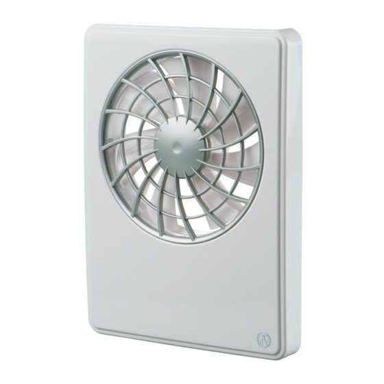
Smart Wi-Fi DELIVERY SET 1 pc. Logo 1 pc. Spigot Ø 100 mm 1 pc. Spigot Ø 125 mm 1 pc. Screws and dowels 4 pcs. User’s manual 1 pc. Packing box 1 pc. TECHNICAL DATA The product described herein is the axial fan made of high-quality plastic designed for extract ventilation within small and medium- sized residential premises that are heated during the winter period. - Page 7 Smart Wi-Fi TECHNICAL DATA Maximum Spigot Air flow, Noise level at, Model Speed Current, [A] RPM, [min-1] diameter [m3/h] 3 m [dBA] power, [W] 24 hours 0.02 Silent 0.04 1650 0.06 2150 Smart Wi-Fi 24 hours 0.03 Silent 0.04 1350 0.07...
- Page 8 Smart Wi-Fi OVERALL DIMENSIONS FAN OPERATION MODES Standby mode – the fan motor does not rotate, the rotation is activated when the 24 hours mode is activated by a mobile application or by a signal from a temperature/humidity/motion or an external switch.
-
Page 9: Installation And Set-Up
Smart Wi-Fi INSTALLATION AND SET-UP 1. In case of vertical mounting the fan must be protected against 2. Before starting the installation, make sure all electricity has water and condensation collecting inside the fan. been turned off! Fan installation with direct air discharge upwards is not allowed. - Page 10 Smart Wi-Fi 5. Lead the power cable to the ventilation hole, drill the mounting 6. Fix the fan with the screws. holes and install the dowels. 7. Remove the cover to access the terminal block and connect 8. Supply power to the fan.
-
Page 11: Connection To Power Mains
Smart Wi-Fi CONNECTION TO POWER MAINS The fan is rated for connection to single-phase AC 100-240 V/50 (60) Hz. TERMINAL DESIGNATIONS ON WIRING DIAGRAMS: L – phase N – 0 LI – output for external load connection LT – fan speed control circuit SK –... -
Page 12: Unit Control
Smart Wi-Fi UNIT CONTROL The fan is controlled by the application on the mobile device. The application is available for download at Store, Play Market or via the QR code. App Store download link Play Market download link By default, the fan operates as a Wi-Fi access point. - Page 13 Smart Wi-Fi Select a desired connection type. 1. Enter the app menu. 2. Select Connection-Connection list. 3. If the fan is operating in Wi-Fi access point mode, select the Default connection. Connection is initiated automatically. 4. If the fan is connected to a home Wi-Fi network, search for devices on the network.
- Page 14 Smart Wi-Fi WI-FI PARAMETER SETUP Go to the application menu on your mobile device Menu – Connection – Wi-Fi setup. Then, press Receive. The screen will display the current Wi-Fi parameter settings. Select one of the Wi-Fi operation modes: Access point or Client.
- Page 15 Smart Wi-Fi SPECIAL «SETUP MODE/RESET» To restore the Wi-Fi password or connect to the fan in order to change the settings, Setup Mode is provided . To enter the Setup Mode, press and hold the button below the front panel of the ventilator for 5 seconds until the LED starts blinking blue.
- Page 16 Smart Wi-Fi ACCESS TO THE BUTTON Indicators: — turn-on or turn-off delay timer operation indicator — humidity exceeding indicator — temperature rise indicator — warning indicator (battery needs replacing) — external switch operation indicator — motion sensor indicator — Interval ventilation mode indicator —...
- Page 17 Smart Wi-Fi CLOCK WITH CURRENT TIME To set the clock for the current time, go to the Settings - Current time menu. Current time is used to indicate the time and operation of some scheduled modes (see Modes). When the fan is disconnected from the mains, the clock continues to operate from an external power source.
- Page 18 Smart Wi-Fi FACTORY SETTINGS RESTORE To restore the factory settings, go to the Settings – Setting reset menu. Then click Reset to factory settings. After restore, connection with device may be lost due to Wi-Fi settings reset. If necessary, reset your Wi-Fi connection.
- Page 19 Smart Wi-Fi SENSOR OPERATION SETUP When setting up the sensors, take into account that it is possible to select the operation by a temperature sensor or any other sensors (humidity, motion an external switch). ADJUSTMENT OF OPERATION BASED ON TEMPERATURE SENSOR Go to the Settings –...
- Page 20 Smart Wi-Fi ADJUSTMENT OF OPERATION BASED ON HUMIDITY SENSOR Go to the Settings – Sensors menu and deactivate the temperature sensor, then select one of the humidity sensor operating modes. Three modes are available: Disable – the humidity sensor is deactivated.
- Page 21 Smart Wi-Fi ADJUSTMENT OF OPERATION BASED ON MOTION SENSOR Go to the Settings – Sensors menu and activate the motion sensor. If this sensor selection is inactive, then deactivate the temperature sensor first. When the motion sensor is triggered, the turn-on delay timer is switched on, and the fan switches to the Silent speed.
- Page 22 Smart Wi-Fi OPERATION MODES To configure the operating modes, go to the Settings – Modes menu. 24 hours – when this mode is activated, the fan is on and operates at minimum speed. When sensors are triggered, the fan will go to a higher speed.
- Page 23 Smart Wi-Fi TIMER SETUP To configure the timers, go to the Settings – Timers menu. Turn-off delay timer is designed to prolong the fan operation in the mode caused by sensor triggering or Boost Mode activation, after sensor threshold values are not exceeded any more.
-
Page 24: Storage And Transportation Regulations
Smart Wi-Fi BATTERY REPLACEMENT If the battery is low or dead, the corresponding warning indicator appears on the home page in the application (see page 16). If such an indicator appears on the home page, replace the battery. To do this, power off the fan, remove the front panel and the cover protecting the control circuit board. -
Page 25: Technical Maintenance
Smart Wi-Fi TECHNICAL MAINTENANCE 1. Turn the lock button on the fan to the lock position. 2. Remove the front panel. Fan operation will be locked. Clean the fan blades with a soft dry cloth or brush. WARNING! The locking does not remove the voltage from the fan power terminals! 3. -
Page 26: Manufacturer's Warranty
Smart Wi-Fi MANUFACTURER’S WARRANTY The product is in compliance with EU norms and standards on low voltage guidelines and electromagnetic compatibility. We hereby declare that the product complies with the provisions of Electromagnetic Council Directive 2014/30/EU, Low Voltage Directive 2014/35/ EU and CE-marking Directive 93/68/EEC. - Page 27 Smart Wi-Fi • External damage to the unit casing (excluding external modifications as required for installation) and internal components caused by the user. • Redesign or engineering changes to the unit. • Replacement and use of any assemblies, parts and components not approved by the manufacturer.
- Page 28 Smart Wi-Fi www.blaubergventilatoren.de...
- Page 29 Smart Wi-Fi www.blaubergventilatoren.de...
- Page 30 Smart Wi-Fi Sold by Quality Inspector’s Stamp (name and stamp of the seller) Manufacture Date Purchase Date www.blaubergventilatoren.de...
- Page 31 Smart Wi-Fi www.blaubergventilatoren.de...
- Page 32 B168EN-02 www.blaubergventilatoren.de...
Need help?
Do you have a question about the Smart Wi-Fi and is the answer not in the manual?
Questions and answers