Table of Contents
Advertisement
Quick Links
Owner's Instruction and Operation Manual
Model Number:
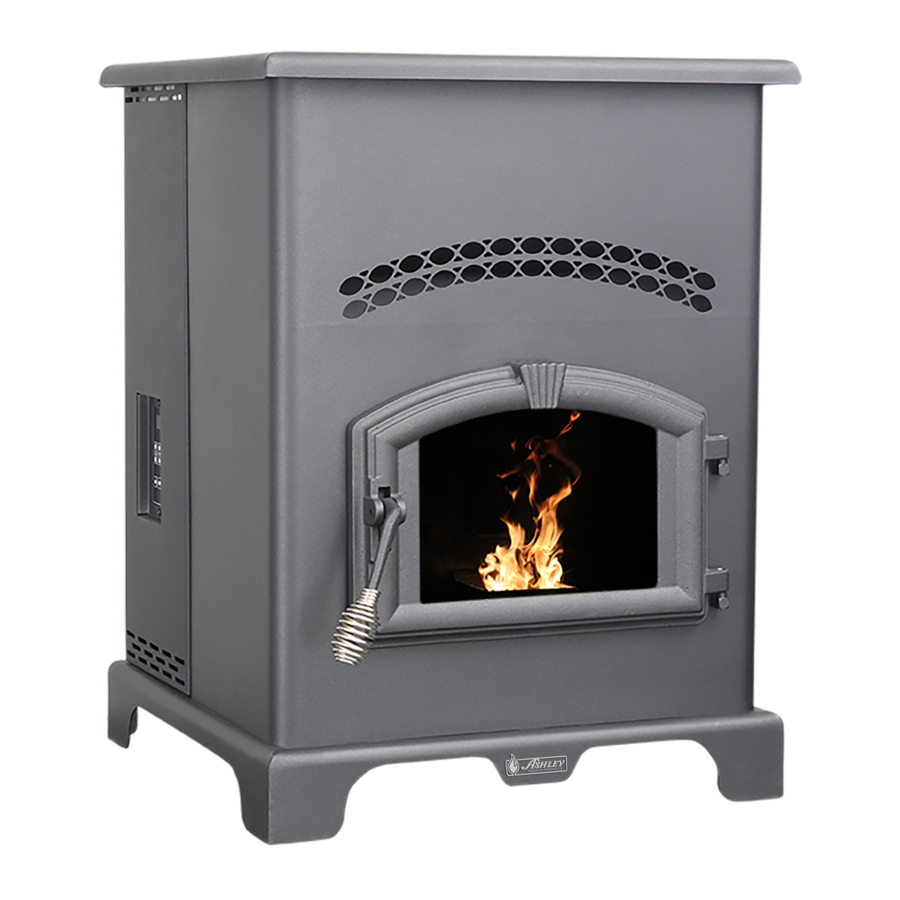
VG130
Report #: F20-570
Certified to ASTM E1509-12 (2017),
and Certified to ULC-S627-00-REV1
Mobile Home Approved
* All Pictures In This Manual Are For Illustrative Purposes Only. Actual Product May Vary.
Save These Instructions In A Safe Place For Future Reference.
SAFETY NOTICE: If this heater is not properly installed, a house fire may result. For
your safety, follow the installation instructions. Never use make-shift compromises
during the installation of this heater. Contact local building or fire officials about
permits, restrictions and installation requirements in your area. NEVER OPERATE THIS
PRODUCT WHILE UNATTENDED.
CAUTION! Please read this entire manual before you install or use your new room
heater. Failure to follow instructions may result in property damage, bodily injury, or
even death. Improper Installation Will Void Your Warranty!
U.S. Environmental Protection Agency
Certified to comply with 2020 particulate
emissions standards.
© 2021 United States Stove Company, 227 Industrial Park Rd., South Pittsburg, TN 37380
R
THIS MANUAL IS SUBJECT TO CHANGE WITHOUT NOTICE.
CALIFORNIA PROPOSITION 65 WARNING:
This product can expose you to chemicals
including carbon monoxide, which is known to the
State of California to cause cancer, birth defects,
and/or other reproductive harm. For more
information, go to
853140K-0302K
www.P65warnings.ca.gov
Ph. 800-750-2723
Advertisement
Table of Contents

Subscribe to Our Youtube Channel
Related Manuals for Vogelzang International VG130


Summary of Contents for Vogelzang International VG130
- Page 1 Owner’s Instruction and Operation Manual Model Number: VG130 Report #: F20-570 Certified to ASTM E1509-12 (2017), and Certified to ULC-S627-00-REV1 Mobile Home Approved * All Pictures In This Manual Are For Illustrative Purposes Only. Actual Product May Vary. 853140K-0302K Save These Instructions In A Safe Place For Future Reference.
-
Page 2: Specifications
Your pellet stove has been safety tested and listed to ASTM E1509-12 (2017), ULC-S627-00. This manual describes the installation and operation of the Vogelzang, VG130 pellet stove. This heater meets the 2020 U.S. Environmental Protection Agency’s crib wood emission limits for wood-heaters sold after May 15, 2020. Under specific EPA test conditions burning wood pellet fuel this heater has been shown to deliver heat at a rate of 8,932 to 25,701 Btu/hr. -
Page 3: Installation Checklist
INSTALLATION CHECKLIST Your Wood Stove should be installed by a qualified installer only. An NFI qualified Installer can be found at www.nficertified. org/public/find-an-nfi-pro/ CUSTOMER SERVICE 1-800-750-2723 ext 5050 Text to 423-301-5624 Email to: Customerservice@usstove.com COMMISSIONING CHECKLIST This checklist is to be completed in full by the qualified person who installs this unit. Keep this page for future reference. Failure to install and commission according to the manufacturer’s instructions and complete this checklist will invalidate the warranty. -
Page 4: Installation
INSTALLATION CAUTION: SAFETY NOTICE BURNING FUEL CREATES CARBON MONOXIDE AND • IF THIS STOVE IS NOT PROPERLY INSTALLED, A CAN BE HAZARDOUS TO YOUR HEALTH IF NOT HOUSE FIRE MAY RESULT. TO REDUCE THE RISK OF PROPERLY VENTED. FIRE, FOLLOW THE INSTALLATION INSTRUCTIONS. •... -
Page 5: Outside Air Supply
INSTALLATION installation. A Floor Protector of 1” (26 mm) thick is recommended for this installation. Canadian installations require 18” (450 mm) in front of the unit. E Backwall to unit F Sidewall to flue PARALLEL Dimensions Sidewall to top edge of unit A Rear (through wall) CORNER... - Page 6 INSTALLATION WARNING! DO NOT INSTALL IN SLEEPING ROOM. IMPORTANT: CAUTION! THE STRUCTURAL INTEGRITY OF THE THIS UNIT IS EQUIPPED WITH A NEGATIVE DRAFT MOBILE HOME FLOOR, WALL, AND CEILING/ROOF SYSTEM THAT PULLS AIR THROUGH THE BURN POT MUST BE MAINTAINED. AND PUSHES THE EXHAUST OUT OF THE DWELLING.
-
Page 7: Pellet Vent Installation
INSTALLATION PELLET VENT INSTALLATION A. Minimum 4-foot (1.22m) clearance below or beside any door or window that opens. The installation must include a clean-out tee to enable collection of fly ash and to permit periodic cleaning of the B. Minimum 1-foot (0.3m) clearance above any door or exhaust system. -
Page 8: Through The Roof/Ceiling Installation
INSTALLATION kit that will handle most of this installation, which will installation. Never terminate the end vent under a deck, in include a wall thimble that will allow the proper clearance an alcove, under a window, or between two windows. We through a combustible wall. -
Page 9: How Your Stove Works
OPERATION INSTRUCTIONS NEVER OPERATE THIS PRODUCT WHILE UNATTENDED HOW YOUR STOVE WORKS continues, the fuel in the burn pot will be consumed and the fire will go out. Matching the amount of air required for proper combustion to the fuel rate is the primary objective 4 Digit Display in effectively burning pellets of various brands and qualities in your stove. -
Page 10: Control Panel Overview
OPERATION INSTRUCTIONS • During start-up ignition must occur within 12 minutes or this speed can be manually operated by pressing the the stove will error out and show E3. “Draft Fan” arrows up or down. “Draft Fan” when pressed, the display will show “Df-A”, which is automatic. Press the •... -
Page 11: Thermostat Hook-Up
OPERATION INSTRUCTIONS THERMOSTAT HOOK-UP The Jumper Must Be Removed First 1. Put female terminals on the lead wires to your low voltage thermostat. 2. Plug one thermostat lead onto each of the terminal posts on the circuit board. IMPORTANT NOTE: The purpose of the T’Stat is make stove... -
Page 12: Proper Fuel
OPERATION INSTRUCTIONS standard (minimum of 40 lbs density per cubic ft, 1/4” to WARNING: 5/16” diameter, length no greater than 1.5”, not less than • DO NOT USE CHEMICALS OR FLUIDS TO START 8,200 BTU/lb, moisture under 8% by weight, ash under 1% THE FIRE - NEVER USE GASOLINE, GASOLINE- by weight, and salt under 300 parts per million). -
Page 13: Pre-Start-Up Check
OPERATION INSTRUCTIONS PRE-START-UP CHECK your stove. The stove will have to fully shut down and turn off before you will be able to restart the stove. Remove burn pot, making sure it is clean and none of the air holes are plugged. Clean the firebox, and then reinstall ROOM AIR FAN burn pot. -
Page 14: Interior Chambers
OPERATION INSTRUCTIONS Turning your stove off is a matter of pressing the “POWER” will shut down and show “E2” on the two digit display. The button on the display board. The green light will turn back stove has to fully shut down before restarting. to red when the “POWER”... -
Page 15: Maintenance
MAINTENANCE NEVER OPERATE THIS PRODUCT WHILE UNATTENDED FLY ASH CAUTION: This accumulates in the horizontal portion of an exhaust • FAILURE TO CLEAN AND MAINTAIN THIS UNIT AS run. Though non-combustible, it may impede the normal INDICATED CAN RESULT IN POOR PERFORMANCE, exhaust flow. -
Page 16: Painted Surfaces
MAINTENANCE out the chimney, exposure to the gases in closed or scratches appear, or you wish to renew your paint, contact confined areas can be dangerous. Make sure you stove your authorized dealer to obtain a can of suitable high- gaskets and chimney joints are in good working order temperature paint. -
Page 17: Fall Start Up
MAINTENANCE FALL START UP MAINTENANCE SCHEDULE Prior to starting the first fire of the heating season, check Use the following as a guide under average use conditions. the outside area around the exhaust and air intake systems Gaskets around door and door glass should be inspected for obstructions. -
Page 18: Troubleshooting
TROUBLE SHOOTING • Disconnect the power cord before performing any maintenance! NOTE: Turning the ON/OFF Switch to ”OFF” does not disconnect all power to the electrical components of the stove. • Never try to repair or replace any part of the stove unless instructions for doing so are given in this manual. All other work should be done by a trained technician. -
Page 19: Display Indicators
TROUBLE SHOOTING Error Code Error Description Possible Causes Inadequate ventilation. The high limit temperature sensor has Room fan failure. Err1 tripped. Exhaust Blockage. Electrical Open in wiring. Hopper Empty. Auger output failure or jam. Flame of fuel quality caused fire to burn too slowly or go Stove ran out of fuel during normal Err2 out. -
Page 20: Parts List
PARTS LIST © 2021 United States Stove Company... - Page 21 PARTS LIST Part # Description 80472 Distribution Blower 69524 Feed Door Assembly 88106 Distribution Blower Gasket 891372 Door Hinge Pad 25774 Pressure Switch Bracket 25080B Feed Door Latch 80549 Pressure Switch 69693 Burnpot Housing Weldment 89586 Nipple 86624 Burnpot Assembly 891121 Silicone Hose 3”...
- Page 22 PARTS LIST Part # Description 891135 Spring Handle 25492 Handle, Door 83506 3/8 x 1-1/4 Roll Pin 25507 Feed Door 88066 5/8” Rope Gasket 4.5 ft 891053 Door Glass 25521 Top Glass Retainer 25520 Bottom Glass Retainer 25393 Glass Retainer To order parts: Call 1-800-750-2723 Ext 5051 or Email to: parts@usstove.com...
-
Page 23: Wiring Diagram
WIRING DIAGRAM BLACK GRAY ENSURE THE WIRES ARE CONNECTED TO THE BOTTOM TWO PRONGS OF THE HOPPER SWITCH AS SHOWN. CORRECT WRONG HOW TO ORDER REPAIR PARTS For Parts Assistance Call: 800-750-2723 Ext 5051 or Email: parts@usstove.com The information in this owner’s manual is specific to your unit. When ordering replacement parts the information in this manual will help to ensure the correct items are ordered. -
Page 24: Service Record
SERVICE RECORD It is recommended that your heating system is serviced regularly and that the appropriate Service Interval Record is completed. SERVICE PROVIDER Before completing the appropriate Service Record below, please ensure you have carried out the service as described in the manufacturer’s instructions.
Need help?
Do you have a question about the VG130 and is the answer not in the manual?
Questions and answers