Table of Contents
Advertisement
Quick Links
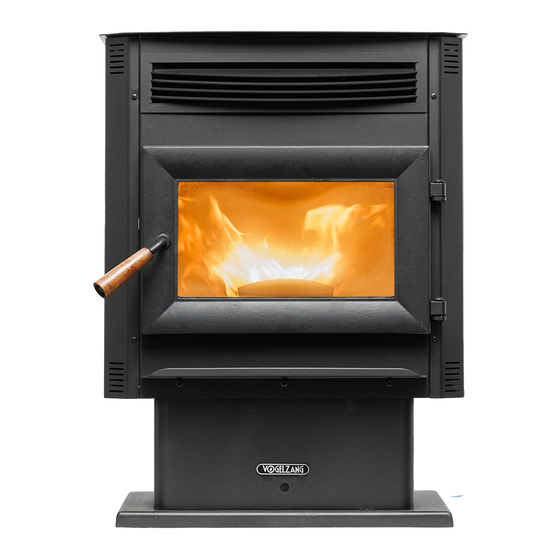
Owner's Instruction and Operation Manual
Model Number:
VG5717-P
Report #: F22-777
Certified to ASTM E1509-12 (2017)
and Certified to ULC-S627-00-REV1
Mobile Home Approved
* All Pictures In This Manual Are For Illustrative Purposes Only. Actual Product May Vary.
Save These Instructions In A Safe Place For Future Reference.
SAFETY NOTICE: If this heater is not properly installed, a house fire may result. For
your safety, follow the installation instructions. Never use make-shift compromises
during the installation of this heater. Contact local building or fire officials about
permits, restrictions and installation requirements in your area. NEVER OPERATE THIS
PRODUCT WHILE UNATTENDED.
CAUTION! Please read this entire manual before you install or use your new room
heater. Failure to follow instructions may result in property damage, bodily injury, or
even death. Improper Installation Will Void Your Warranty!
U.S. Environmental Protection Agency
Certified to comply with 2020 particulate
emissions standards.
© 2022 United States Stove Company, 227 Industrial Park Rd., South Pittsburg, TN 37380
R
THIS MANUAL IS SUBJECT TO CHANGE WITHOUT NOTICE.
CALIFORNIA PROPOSITION 65 WARNING:
This product can expose you to chemicals
including carbon monoxide, which is known to the
State of California to cause cancer, birth defects,
and/or other reproductive harm. For more
information, go to
853928-1503L
www.P65warnings.ca.gov
Ph. 800-750-2723
Advertisement
Table of Contents

Subscribe to Our Youtube Channel
Related Manuals for Vogelzang International VG5717-P


Summary of Contents for Vogelzang International VG5717-P
- Page 1 Owner’s Instruction and Operation Manual Model Number: VG5717-P Report #: F22-777 Certified to ASTM E1509-12 (2017) and Certified to ULC-S627-00-REV1 Mobile Home Approved * All Pictures In This Manual Are For Illustrative Purposes Only. Actual Product May Vary. 853928-1503L Save These Instructions In A Safe Place For Future Reference.
- Page 2 INTRODUCTION Your pellet stove has been approved for installation in the USA and Canada. It may also be installed in a manufactured or mobile home. Your stove is Certified to ASTM E1509-12 (2017) and Certified. This manual describes the installation and operation of the Ashley, pellet stove.
-
Page 3: Installation Checklist
INSTALLATION CHECKLIST Your Wood Stove should be installed by a qualified installer only. An NFI qualified Installer can be found at www.nficertified. org/public/find-an-nfi-pro/ CUSTOMER SERVICE 1-800-750-2723 ext 5050 Text to 423-301-5624 Email to: Customerservice@usstove.com COMMISSIONING CHECKLIST This checklist is to be completed in full by the qualified person who installs this unit. Keep this page for future reference. Failure to install and commission according to the manufacturer’s instructions and complete this checklist will invalidate the warranty. - Page 4 ASSEMBLY INSTRUCTIONS FOR CUSTOMER SERVICE CALL: 800-750-2723 EXT 5050 1. Pull the factory installed wires out of the top of the 3. Connect the factory installed wiring harnesses to the stove. There will be two wire harnesses, as shown. control panel as shown. 2.
-
Page 5: Installation
INSTALLATION FOR CUSTOMER SERVICE CALL: 800-750-2723 EXT 5050 CAUTION: SAFETY NOTICE BURNING FUEL CREATES CARBON MONOXIDE AND • IF THIS STOVE IS NOT PROPERLY INSTALLED, A CAN BE HAZARDOUS TO YOUR HEALTH IF NOT HOUSE FIRE MAY RESULT. TO REDUCE THE RISK OF PROPERLY VENTED. -
Page 6: Installation Options
INSTALLATION INSTALLATION OPTIONS CLEARANCES Freestanding Unit - supported by pedestal/legs and Your pellet stove has been tested and listed for installation placed on a non-combustible floor surface in compliance in residential, mobile home in accordance with the with clearance requirements for a freestanding stove clearances given below. -
Page 7: Outside Air Supply
INSTALLATION OUTSIDE AIR SUPPLY • Vent must be 3 or 4-inch “PL” Vent and must extend a (OPTIONAL, UNLESS INSTALLING minimum or 36” (914 mm) above the roof line of the IN A MOBILE HOME) mobile home and must be installed using a certified Depending on your location and home construction, ceiling fire stop and rain cap. -
Page 8: Importance Of Proper Draft
INSTALLATION IMPORTANCE OF PROPER DRAFT that can build up a concentration of fumes. Termination in one of these areas can also lead to unpredictable pressure Draft is the force which moves air from the appliance up situations with the appliance, and could result in improper through the chimney. - Page 9 INSTALLATION HORIZONTAL EXHAUST VENT INSTALLATION Must be a minimum of 3 foot (0.91m) above the roof and 2 foot (0.61m) above the highest point or the roof 1. Locate your pellet stove in a location which meets the within 10 feet (3.05m). requirements of this manual, but in an area where it does not interfere with the house framing, wiring, etc.
-
Page 10: Through The Wall Installation
INSTALLATION THROUGH WALL INSTALLATION kit that will handle most of this installation, which will (RECOMMENDED INSTALLATION) include a wall thimble that will allow the proper clearance through a combustible wall. Once outside the structure, a 3” (76 mm) clearance should be maintained from the outside wall and a clean out tee should be placed on the pipe with a 90-degree turn away from the house. - Page 11 INSTALLATION THROUGH ROOF/CEILING INSTALLATION • When venting the heater through the ceiling, the pipe is connected the same as through the wall, except the clean-out tee is always on the inside of the house, and a 3” (76 mm) adapter is added before the clean-out tee. •...
- Page 12 OPERATION INSTRUCTIONS NEVER OPERATE THIS PRODUCT WHILE UNATTENDED PANEL / REMOTE CONTROLS C. °C / °F Button • The °C / °F button changes the two digit display from degrees Celsius to degrees Fahrenheit. NOTE: Operation range of this D. MODE (M/T) BUTTON remote is within 16-1/12 ft.
-
Page 13: Proper Fuel
OPERATION INSTRUCTIONS PROPER FUEL This heater is designed to burn only PFI Premium grade pellets. DO NOT BURN: ATTENTION: 1. Garbage; THIS APPLIANCE IS DESIGNED FOR THE USE 2. Lawn clippings or yard waste; OF PELLETIZED FUEL THAT MEET OR EXCEED 3. - Page 14 OPERATION INSTRUCTIONS • Make sure the burn pot is free of pellets. • DO NOT open the viewing door. CAUTION: • DO NOT OPERATE YOUR STOVE WITH THE • DO NOT add pellets to the burn pot by hand. VIEWING DOOR OPEN. THE AUGER WILL NOT NOTE: During the first few fires, your stove will emit an odor FEED PELLETS UNDER THESE CIRCUMSTANCES as the high-temperature paint cures or becomes seasoned...
-
Page 15: Shutdown Procedure
OPERATION INSTRUCTIONS REFUELING B. In case of a malfunctioning convection blower, the high-temperature snap disc will automatically shut down the auger, preventing the stove from overheating. CAUTION: • THE HOPPER AND STOVE TOP WILL BE HOT NOTE: On some units, once tripped, like a circuit breaker, DURING OPERATION;... - Page 16 OPERATION INSTRUCTIONS It is possible that creosote may accumulate in the exhaust fan therefore, this must be brushed clean. The exhaust fan can be found behind the left side panel (facing the front of the heater), the circulation fan can be found behind the right side panel.
-
Page 17: Maintenance
MAINTENANCE NEVER OPERATE THIS PRODUCT WHILE UNATTENDED exhaust flow. It should therefore be periodically removed. CAUTION: ASH REMOVAL & DISPOSAL • FAILURE TO CLEAN AND MAINTAIN THIS UNIT AS INDICATED CAN RESULT IN POOR PERFORMANCE, SAFETY HAZARDS, FIRE, AND EVEN DEATH. CAUTION: •... -
Page 18: Painted Surfaces
MAINTENANCE BLOWER MOTORS FALL START UP Clean the air holes on the motors of both the exhaust and Prior to starting the first fire of the heating season, check distribution blowers annually. Remove the exhaust blower the outside area around the exhaust and air intake systems from the exhaust duct and clean out the internal fan blades for obstructions. -
Page 19: Troubleshooting Guide
TROUBLESHOOTING GUIDE When your stove acts out of the ordinary, the first reaction is to call for help. This guide may save time and money by enabling you to solve simple problems yourself. Problems encountered are often the result of only five factors: 1) poor fuel;... - Page 20 TROUBLESHOOTING GUIDE Display is Flashing “E2” Possible Causes Possible Remedies: (Unplug stove first when possible) Unhook air hose from the air switch and blow through it. If air Airflow switch hose or stove attachment pipes flows freely, the hose and tube are fine. If air will not flow throw for hose are blocked.
- Page 21 TROUBLESHOOTING GUIDE Display is Flashing “E3” Possible Causes Possible Remedies: (Unplug stove first when possible) The hopper is out of pellets Refill the hopper. The air dampener is too far open for a low feed If on the low setting, you may need to close the dampener all the setting way.
- Page 22 TROUBLESHOOTING GUIDE Display is Flashing “E4” Possible Causes Possible Remedies: (Unplug stove first when possible) The air inlet, burnpot, interior combustion air Follow all cleaning procedures in the maintenance section of the chambers, combustion blower, or exhaust pipe owner’s manual. are blocked with ash or foreign material.
- Page 23 TROUBLESHOOTING GUIDE Stove Feeds Pellets, But Will Not Ignite Possible Causes Possible Remedies: (Unplug stove first when possible) In some situations it may be necessary to have the damper Air damper open too far for ignition. completely closed for ignition to take place. After there is a flame, the damper can then be adjusted for the desired feed setting.
-
Page 24: Repair Parts
REPAIR PARTS NOTE: NUMBERS 4, 6, &16 ARE NOT YET SHOWN Part # Description 88174 1/8 X 1 Window Gasket W/Adhesive 7.28 ft 893159 Clear Glass 88324 1” Rope Gasket 5.17 ft 80780 IR Remote 893629 Burnpot Assembly 80491 Microswitch 80882 Control Board Assembly 80549... -
Page 25: Wiring Diagram
WIRING DIAGRAM Ensure the wires are connected to the bottom two prongs of the hopper switch as shown. CORRECT WRONG HOW TO ORDER REPAIR PARTS For Parts Assistance Call: 800-750-2723 Ext 5051 or Email: parts@usstove.com The information in this owner’s manual is specific to your unit. When ordering replacement parts the information in this manual will help to ensure the correct items are ordered. -
Page 26: Service Record
SERVICE RECORD It is recommended that your heating system is serviced regularly and that the appropriate Service Interval Record is completed. SERVICE PROVIDER Before completing the appropriate Service Record below, please ensure you have carried out the service as described in the manufacturer’s instructions. - Page 27 NOTES © 2022 United States Stove Company...
Need help?
Do you have a question about the VG5717-P and is the answer not in the manual?
Questions and answers