Table of Contents
Advertisement
Quick Links
Owner's Instruction and Operation Manual
Model Number:
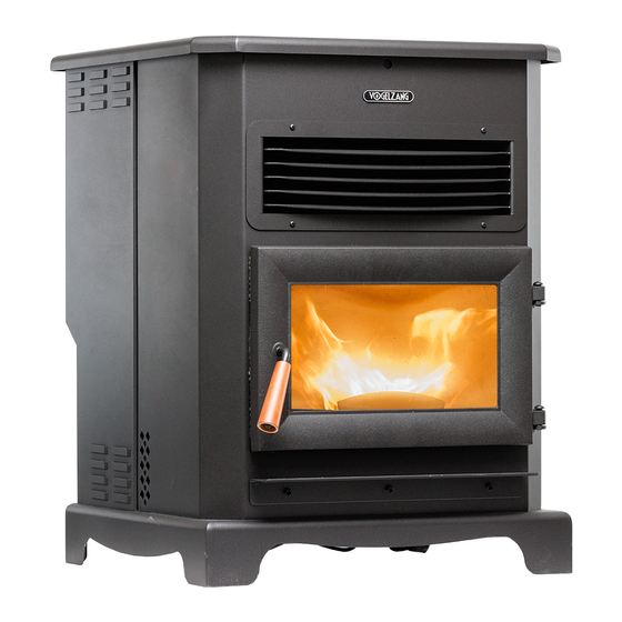
VG5722
Report #: F22-782
Certified to ASTM E1509-12 (2017),
and Certified to ULC-S627-00-REV1
Mobile Home Approved
* All Pictures In This Manual Are For Illustrative Purposes Only. Actual Product May Vary.
Save These Instructions In A Safe Place For Future Reference.
SAFETY NOTICE: If this heater is not properly installed, a house fire may result. For
your safety, follow the installation instructions. Never use make-shift compromises
during the installation of this heater. Contact local building or fire officials about
permits, restrictions and installation requirements in your area. NEVER OPERATE THIS
PRODUCT WHILE UNATTENDED.
CAUTION! Please read this entire manual before you install or use your new room
heater. Failure to follow instructions may result in property damage, bodily injury, or
even death. Improper Installation Will Void Your Warranty!
U.S. Environmental Protection Agency
Certified to comply with 2020 particulate
emissions standards.
© 2022 United States Stove Company, 227 Industrial Park Rd., South Pittsburg, TN 37380
R
THIS MANUAL IS SUBJECT TO CHANGE WITHOUT NOTICE.
CALIFORNIA PROPOSITION 65 WARNING:
This product can expose you to chemicals
including carbon monoxide, which is known to the
State of California to cause cancer, birth defects,
and/or other reproductive harm. For more
information, go to
853932B-3005L
www.P65warnings.ca.gov
Ph. 800-750-2723
Advertisement
Table of Contents

Subscribe to Our Youtube Channel
Related Manuals for Vogelzang International VG5722


Summary of Contents for Vogelzang International VG5722
- Page 1 Owner’s Instruction and Operation Manual Model Number: VG5722 Report #: F22-782 Certified to ASTM E1509-12 (2017), and Certified to ULC-S627-00-REV1 Mobile Home Approved 853932B-3005L * All Pictures In This Manual Are For Illustrative Purposes Only. Actual Product May Vary. Save These Instructions In A Safe Place For Future Reference.
- Page 2 INTRODUCTION Your pellet stove has been safety tested and listed to ASTM E1509-12 (2017) and ULC-S627-00. This manual describes the installation and operation of the pellet stove. This heater meets the 2020 U.S. Environmental Protection Agency’s emission limits for wood-heaters sold after May 15, 2020. Under specific EPA test conditions burning wood pellet fuel this heater has been shown to deliver heat at a rate of 32,591 to 13,640 Btu/hr.
-
Page 3: Installation Checklist
INSTALLATION CHECKLIST Your Wood Stove should be installed by a qualified installer only. An NFI qualified Installer can be found at www.nficertified. org/public/find-an-nfi-pro/ CUSTOMER SERVICE 1-800-750-2723 ext 5050 Text to 423-301-5624 Email to: Customerservice@usstove.com COMMISSIONING CHECKLIST This checklist is to be completed in full by the qualified person who installs this unit. Keep this page for future reference. Failure to install and commission according to the manufacturer’s instructions and complete this checklist will invalidate the warranty. -
Page 4: Installation
INSTALLATION ATTENTION: SAFETY NOTICE • A WORKING SMOKE DETECTOR MUST • IF THIS STOVE IS NOT PROPERLY INSTALLED, A INSTALLED IN THE SAME ROOM AS THIS PRODUCT. HOUSE FIRE MAY RESULT. TO REDUCE THE RISK OF • INSTALL A SMOKE DETECTOR ON EACH FLOOR OF FIRE, FOLLOW THE INSTALLATION INSTRUCTIONS. - Page 5 INSTALLATION FOR CUSTOMER SERVICE CALL: 800-750-2723 EXT 5050 1. Pull the factory installed wires out of the top of the 3. Connect the factory installed wiring harnesses to the stove. There will be two wire harnesses, as shown. control panel as shown. 2.
-
Page 6: Installation Options
INSTALLATION INSTALLATION OPTIONS restrictions. Any reduction in clearance to combustibles may only be done by means approved by a regulatory Freestanding Unit - supported by pedestal/legs and authority. placed on a non-combustible floor surface in compliance with clearance requirements for a freestanding stove installation. -
Page 7: Outside Air Supply
INSTALLATION OUTSIDE AIR SUPPLY a serrated or star washer to penetrate paint or protective (OPTIONAL, UNLESS coating to ensure grounding. INSTALLING IN A MOBILE HOME) Depending on your location and home construction, • Vent must be 3 or 4-inch “PL” Vent and must extend a outside air may be necessary for optimal performance. -
Page 8: Importance Of Proper Draft
INSTALLATION elbows, or two 45-degree and one 90-degree elbow, etc.) Do not terminate the vent in an enclosed or semi-enclosed to maintain adequate draft. area, such as; carport, garage, attic, crawl space, under a sun deck or porch, narrow walkway, or any other location IMPORTANCE OF PROPER DRAFT that can build up a concentration of fumes. - Page 9 INSTALLATION HORIZONTAL EXHAUST VENT H. Minimum 1-foot (0.3m) clearance horizontally from INSTALLATION combustible wall. 1. Locate your pellet stove in a location which meets the Must be a minimum of 3 foot (0.91m) above the roof requirements of this manual, but in an area where it and 2 foot (0.61m) above the highest point or the roof does not interfere with the house framing, wiring, etc.
-
Page 10: Through The Wall Installation
INSTALLATION THROUGH THE WALL INSTALLATION outside wall and a clean out tee should be placed on the (RECOMMENDED INSTALLATION) pipe with a 90-degree turn away from the house. At this point, a 3ft (0.91m) (minimum) section of pipe should be added with a horizontal cap, which would complete the installation. - Page 11 INSTALLATION VENTING YOUR PELLET STOVE INTO AN EXISTING CLASS A 6” CHIMNEY SYSTEM 1. You must have the existing chimney system cleaned and/ or inspected by a qualified chimney sweep before proceeding with the installation of your pellet stove. Existing Class ‘A’ 2.
- Page 12 OPERATION INSTRUCTIONS NEVER OPERATE THIS PRODUCT WHILE UNATTENDED PANEL / REMOTE CONTROLS °C / °F Button • The °C / °F button changes the two digit display from degrees Celsius to degrees Fahrenheit. NOTE: Operation range of this MODE (M/T) BUTTON remote is within 16-1/12 ft.
- Page 13 OPERATION INSTRUCTIONS WARNING: standard (minimum of 40 lbs density per cubic ft, 1/4” to 5/16” diameter, length no greater than 1.5”, not less than • DO NOT USE CHEMICALS OR FLUIDS TO START 8,200 BTU/lb, moisture under 8% by weight, ash under 1% THE FIRE - NEVER USE GASOLINE, GASOLINE- by weight, and salt under 300 parts per million).
-
Page 14: Pre-Start-Up Check
OPERATION INSTRUCTIONS PRE-START-UP CHECK OPENING DOOR Remove burn pot, making sure it is clean and none of the CAUTION: air holes are plugged. Clean the firebox, and then reinstall burn pot. Clean door glass if necessary (a dry cloth or •... -
Page 15: Shutdown Procedure
OPERATION INSTRUCTIONS TAMPER WARNING • Heat Exchanger - There are two clean out plates that need to be removed in order to clean the fly ash out This wood heater has a manufacturer-set minimum low of the heat exchanger. Open the door to access the burn rate that must not be altered. -
Page 16: Maintenance
MAINTENANCE NEVER OPERATE THIS PRODUCT WHILE UNATTENDED FLY ASH CAUTION: This accumulates in the horizontal portion of an exhaust • FAILURE TO CLEAN AND MAINTAIN THIS UNIT AS run. Though non-combustible, it may impede the normal INDICATED CAN RESULT IN POOR PERFORMANCE, exhaust flow. -
Page 17: Painted Surfaces
MAINTENANCE DOOR & GLASS GASKETS FALL START UP Inspect the main door and glass window gaskets Prior to starting the first fire of the heating season, check periodically. The main door may need to be removed to the outside area around the exhaust and air intake systems have frayed, broken, or compacted gaskets replaced for obstructions. -
Page 18: Troubleshooting Guide
TROUBLESHOOTING GUIDE When your stove acts out of the ordinary, the first reaction is to call for help. This guide may save time and money by enabling you to solve simple problems yourself. Problems encountered are often the result of only five factors: 1) poor fuel;... - Page 19 TROUBLESHOOTING GUIDE Display is Flashing “E2” Possible Causes Possible Remedies: (Unplug stove first when possible) Unhook air hose from the air switch and blow through it. If air flows Airflow switch hose or stove attachment pipes for freely, the hose and tube are fine. If air will not flow throw the hose, hose are blocked.
- Page 20 TROUBLESHOOTING GUIDE Display is Flashing “E3” Possible Causes Possible Remedies: (Unplug stove first when possible) The hopper is out of pellets Refill the hopper. The air dampener is too far open for a low feed If on the low setting, you may need to close the dampener all the setting way.
- Page 21 TROUBLESHOOTING GUIDE Display is Flashing “E4” Possible Causes Possible Remedies: (Unplug stove first when possible) The air inlet, burnpot, interior combustion air Follow all cleaning procedures in the maintenance section of the chambers, combustion blower, or exhaust pipe owner’s manual. are blocked with ash or foreign material.
- Page 22 TROUBLESHOOTING GUIDE Stove Feeds Pellets, But Will Not Ignite Possible Causes Possible Remedies: (Unplug stove first when possible) In some situations it may be necessary to have the damper Air damper open too far for ignition. completely closed for ignition to take place. After there is a flame, the damper can then be adjusted for the desired feed setting.
- Page 23 TROUBLESHOOTING GUIDE Stove Will Not Feed Pellets, But Fuel Feed Light Comes On As Designed Possible Causes Possible Remedies: (Unplug stove first when possible) Wait for the stove to cool for about 30 - 45 minutes. Locate the High Limit thermodisc and High limit switch has press the reset button on the back of it.
- Page 24 TROUBLESHOOTING GUIDE High Limit Switch Keeps Tripping Possible Causes Possible Remedies: (Unplug stove first when possible) The convection blower is overheating and Clean any dust off of the windings and fan blades. If oiling the blower does not help, the tripping the internal blower may be bad.
-
Page 25: Wiring Diagram
WIRING DIAGRAM Ensure the wires are connected to the bottom two prongs of the hopper switch as shown. CORRECT WRONG HOW TO ORDER REPAIR PARTS For Parts Assistance Call: 800-750-2723 Ext 5051 or Email: parts@usstove.com The information in this owner’s manual is specific to your unit. When ordering replacement parts the information in this manual will help to ensure the correct items are ordered. -
Page 26: Repair Parts
REPAIR PARTS To order parts: Call 1-800-750-2723 Ext 5051 or Email to: parts@usstove.com Part # Description 80869 Ceramic Ignitor Glass Gasket - Flat (3/16T x 80549 Pressure Switch 88174 3/8W) 80867 Distribution Blower 893154 Clear Glass 88106 Distribution Blower Gasket 88324 1”... -
Page 27: Service Record
SERVICE RECORD It is recommended that your heating system is serviced regularly and that the appropriate Service Interval Record is completed. SERVICE PROVIDER Before completing the appropriate Service Record below, please ensure you have carried out the service as described in the manufacturer’s instructions. - Page 28 NOTES © 2022 United States Stove Company...
- Page 29 NOTES © 2022 United States Stove Company...
Need help?
Do you have a question about the VG5722 and is the answer not in the manual?
Questions and answers