Advertisement
Speaker Layout
Figure 1
Row 1
A
Row 2
B
Row 3
Row 4
Figure 2
Low Noise
(55dB-65dB)
Medium Noise
(65dB-75dB
HORN SPEAKER
START
C
PLACEMENT
A
B
C
60 ft.
120 ft.
80 ft.
100 ft.
50 ft.
60 ft.
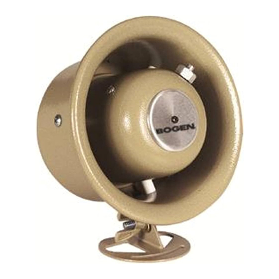
Easy Design Speaker
Model HS7EZ
The layout of the speakers should be planned prior
to installation. Desired mounting height, barring
obstructions, is 15 to 20 feet, with the speakers
angled downward toward the listening area and
facing in the same direction.
Layout starts in one corner of the area. The first
speaker in Row 1 should be positioned a distance
equivalent to (A) (see Figure 2) from the corner
based on the noise level of the area. The next
speaker in Row 1 should be a distance equivalent
to (B) (see Figure 2) from the first speaker. Each
additional speaker in the row should use this same
spacing.
Row 2 starts a distance equivalent to (C) (see
Figure 2) from Row 1 and, like Row 1, each speak-
er should be a distance apart equivalent to (B).
Row 3 starts a distance equivalent to (C) from
Row 2. Continue this pattern of alternating rows
until the area is appropriately covered.
For areas that include high shelving or corridors,
speakers should be installed so that they project
down the aisles between the shelves or down
Volume Setting
through the corridors.
1/2 Rotation
The spacing of the speakers can be adjusted so
that the speakers are evenly spaced in a row.
Full Clockwise
TM
NOTE: Each environment is unique.This layout
plan is general in nature and may not be
applicable for every installation.
Specifications subject to change without notice.
© 1999 Bogen Communications Inc. All rights reserved.
Part No. 54-5071-01 Printed in Korea 9906
Advertisement
Table of Contents

Related Manuals for Bogen Easy Design HS7EZ


Summary of Contents for Bogen Easy Design HS7EZ
- Page 1 NOTE: Each environment is unique.This layout plan is general in nature and may not be applicable for every installation. Specifications subject to change without notice. © 1999 Bogen Communications Inc. All rights reserved. Part No. 54-5071-01 Printed in Korea 9906...
- Page 2 See Figure 2 for the suggested initial set- tings based on the ambient noise level of the environment. Figure 3 Figure 4 Red Wire Black Wire VOLUME CONTROL WIRE CONNECTORS 50 Spring Street, Ramsey NJ 07446 Tel. 201-934-8500, Fax: 201-934-9832 www.bogen.com...
Need help?
Do you have a question about the Easy Design HS7EZ and is the answer not in the manual?
Questions and answers