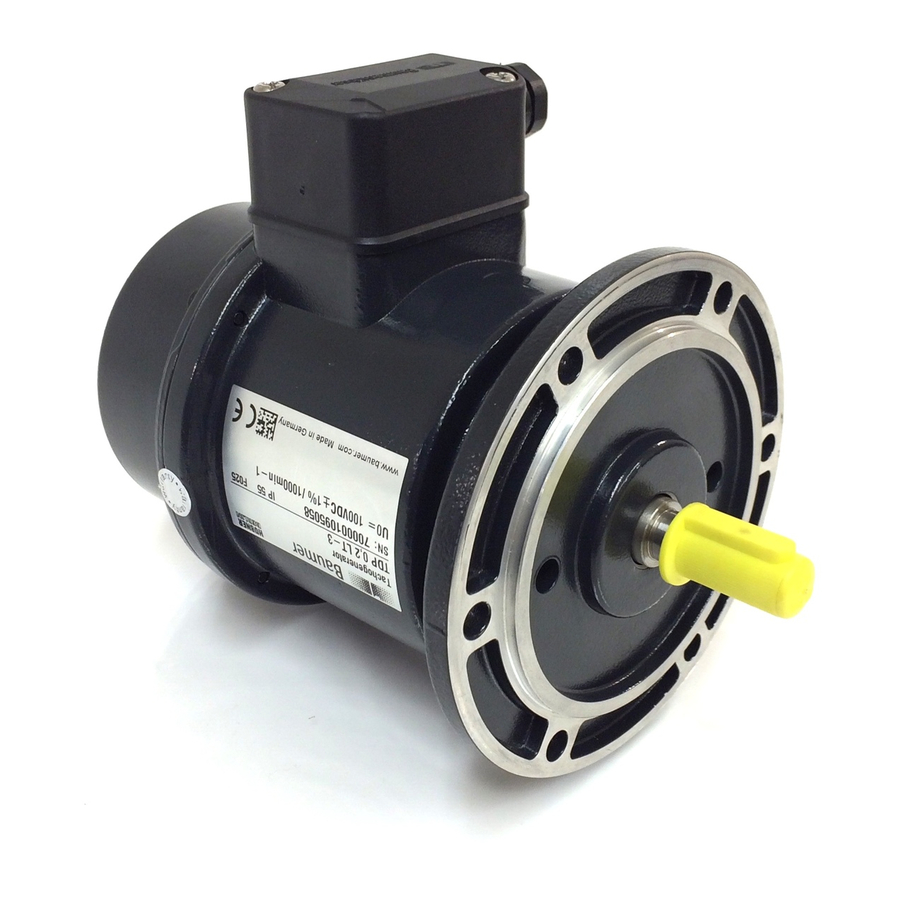
Baumer HUBNER TDP 0,2 Mounting And Operating Instructions
Hide thumbs
Also See for HUBNER TDP 0,2:
- Installation and operating instructions manual (32 pages) ,
- Mounting and operating instructions (32 pages) ,
- Mounting and operating instruction (28 pages)
Table of Contents
Advertisement
Quick Links
Montage- und Betriebsanleitung
Mounting and operating instructions
TDP 0,2 (TDPZ 0,2) + ESL
Kombination
Tachogenerator (Doppel-Tachogenerator) mit
integriertem elektronischen Drehzahlschalter
Combination
Tachogenerator (Twin tachogenerator) with
integrated electronic speed switch
Gehäusefuß B3
Housing foot B3
EURO-Flansch B10
EURO flange B10
Advertisement
Table of Contents

Related Manuals for Baumer HUBNER TDP 0,2


Summary of Contents for Baumer HUBNER TDP 0,2
- Page 1 Montage- und Betriebsanleitung Mounting and operating instructions Gehäusefuß B3 Housing foot B3 EURO-Flansch B10 EURO flange B10 TDP 0,2 (TDPZ 0,2) + ESL Kombination Tachogenerator (Doppel-Tachogenerator) mit integriertem elektronischen Drehzahlschalter Combination Tachogenerator (Twin tachogenerator) with integrated electronic speed switch...
-
Page 2: Table Of Contents
4.3.1 Schritt 2 ................................4.3.2 Schritt 3 ................................. Montagehinweis ............................Maximal zulässige Montagefehler unter Verwendung der Baumer Hübner Federscheibenkupplung K 35 ................Hinweis bei Verwendung einer Klauenkupplung (zum Beispiel „ROTEX®“) ....Abmessungen ................................TDP 0,2 + ESL .............................. 5.1.1 EURO-Flansch B10 .......................... - Page 3 ................................4.3.2 Step 3 ................................Mounting instruction ..........................Maximum permissible mounting tolerance when the Baumer Hübner K 35 spring disk coupling is used ..............Note when using a jaw-type coupling (for example “ROTEX®”) ........Dimensions .................................. TDP 0,2 + ESL ..............................
-
Page 4: Allgemeine Hinweise
Gebrauchte Elektro- und Elektronikgeräte dürfen nicht im Hausmüll entsorgt werden. Das Produkt enthält wertvolle Rohstoffe, die recycelt werden können. Wenn immer möglich sollen Altgeräte lokal am entsprechenden Sammeldepot entsorgt werden. Im Bedarfsfall gibt Baumer den Kunden die Möglichkeit, Baumer-Produkte fachgerecht zu entsor- gen. Weitere Informationen siehe www.baumer.com. Achtung! Beschädigung des auf dem Gerät befindlichen Siegels... -
Page 5: General Notes
Whenever possible, waste electrical and electronic equipment should be disposed locally at the authorized collection point. If necessary, Baumer gives customers the opportunity to dispose of Baumer products profession- ally. For further information see www.baumer.com. -
Page 6: Sicherheitshinweise
Sicherheitshinweise Sicherheitshinweise Verletzungsgefahr durch rotierende Wellen Haare und Kleidungsstücke können von rotierenden Wellen erfasst werden. • Vor allen Arbeiten alle Betriebsspannungen ausschalten und Maschinen stillsetzen. Zerstörungsgefahr durch mechanische Überlastung Eine starre Befestigung kann zu Überlastung durch Zwangskräfte führen. • Die Beweglichkeit des Gerätes niemals einschränken. Unbedingt die Montagehinweise beachten. -
Page 7: Security Indications
Security indications Security indications Risk of injury due to rotating shafts Hair and clothes may become tangled in rotating shafts. • Before all work switch off all voltage supplies and ensure machinery is stationary. Risk of destruction due to mechanical overload Rigid mounting may give rise to constraining forces. -
Page 8: Vorbereitung
Vorbereitung / Preparation Vorbereitung Preparation Lieferumfang Gerät Scope of delivery device Gehäuse TDP 0,2 (TDPZ 0,2) Housing TDP 0,2 (TDPZ 0,2) Gehäuse ESL Housing ESL Vollwelle mit Passfeder Solid shaft with key EURO-Flansch B10 EURO flange B10 Gehäusefuß B3 Housing foot B3 Bürstenhalterung mit Kohlebürsten Brush holder with carbon brushes Kohlebürsten, auch als Zubehör erhältlich:... -
Page 9: Lieferumfang Klemmenkästen
Vorbereitung / Preparation Lieferumfang Klemmenkästen Scope of delivery terminal boxes Klemmenkasten TDP 0,2 (TDPZ 0,2) Terminal box TDP 0,2 (TDPZ 0,2) Klemmenkastendeckel Terminal box cover Torx-/Schlitzschraube M4x32 mm Torx/slotted screw M4x32 mm Kabelverschraubung M20x1,5 Cable gland M20x1,5 für Kabel ø5...13 mm for cable ø5...13 mm Anschlussklemmen, Connecting terminal,... -
Page 10: Zur Montage Erforderlich (Nicht Im Lieferumfang Enthalten)
Vorbereitung / Preparation Zur Montage erforderlich Required for mounting (nicht im Lieferumfang enthalten) (not included in scope of delivery) Anbauvorrichtung, kundenspezifisch Installation fitting, customized Befestigungsschrauben für Anbauvorrichtung Fixing screws for installation fitting ISO 4017, ISO 4017, M6x16 mm M6x16 mm Federscheibenkupplung K 35, Spring disk coupling K 35, als Zubehör erhältlich, siehe Abschnitt 4.5. -
Page 11: Montage
Montage / Mounting Montage Mounting Schritt 1 Step 1 Anzugsmoment: Tightening torque: = 1 Nm 2.5 mm EURO-Flansch B10 EURO flange B10 4.2.1 Schritt 2 4.2.1 Step 2 10 mm Antriebswelle einfetten. Lubricate drive shaft. Die Antriebswelle sollte einen The drive shaft should have as less möglichst kleinen Rundlauffehler runout as possible. -
Page 12: Schritt 4
Montage / Mounting EURO-Flansch B10 EURO flange B10 4.2.3 Schritt 4 4.2.3 Step 4 2.5 mm Anzugsmoment: Tightening torque: = 1.3 ±10 % Nm Gehäusefuß B3 Housing foot B3 4.3.1 Schritt 2 4.3.1 Step 2 * Siehe Seite 5 oder 7 See page 5 or 7 Antriebswelle einfetten. -
Page 13: Schritt 3
Montage / Mounting 4.3.2 Schritt 3 4.3.2 Step 3 Anzugsmoment: Tightening torque: = 1.3 ±10 % Nm 2.5 mm 10 mm * Siehe Seite 5 oder 7 See page 5 or 7 Montagehinweis Mounting instruction Wir empfehlen, das Gerät so zu It is recommended to mount the device montieren, dass der Kabelanschluss with cable connection facing down-... -
Page 14: Maximal Zulässige Montagefehler Unter Verwendung Der Baumer Hübner Federscheibenkupplung K 35
Montage / Mounting Maximal zulässige Montagefehler Maximum permissible mounting toler- unter Verwendung der Baumer Hübner ance when the Baumer Hübner K 35 Federscheibenkupplung K 35 spring disk coupling is used Geräte mit Vollwelle sollten unter Verwen- Devices with a solid shaft should be dung der Baumer Hübner Federschei-... -
Page 15: Hinweis Bei Verwendung Einer Klauenkupplung (Zum Beispiel „Rotex®")
Montage / Mounting Hinweis bei Verwendung einer Klauen- Note when using a jaw-type coupling kupplung (zum Beispiel „ROTEX®“) (for example “ROTEX®”) Eine falsche Montage der Klauenkupplung Incorrect mounting of the jaw-type cou- führt zur Beschädigung des Gerätes. pling can damage the device. Mit einem Tiefenmessschieber die Use a depth gauge to find and observe korrekten Abstände (L, L1), siehe unten,... -
Page 16: Abmessungen
Abmessungen / Dimensions Abmessungen Dimensions TDP 0,2 + ESL TDP 0,2 + ESL 5.1.1 EURO-Flansch B10 5.1.1 EURO flange B10 (61361, 61362) (61361, 61362) Drehrichtung positiv Positive rotating direction 5.1.2 Gehäusefuß B3 5.1.2 Housing foot B3 (61365) (61365) Drehrichtung positiv Positive rotating direction Alle Abmessungen in Millimeter (wenn nicht anders angegeben) All dimensions in millimeters (unless otherwise stated) -
Page 17: Tdpz 0,2 + Esl
Abmessungen / Dimensions TDPZ 0,2 + ESL TDPZ 0,2 + ESL 5.2.1 EURO-Flansch B10 5.2.1 EURO flange B10 (61813, 61814) (61813, 61814) Drehrichtung positiv Positive rotating direction 5.2.2 Gehäusefuß B3 5.2.2 Housing foot B3 Drehrichtung positiv Positive rotating direction Alle Abmessungen in Millimeter (wenn nicht anders angegeben) All dimensions in millimeters (unless otherwise stated) MB079.2 - 11115290 Baumer_TDP02-ESL-TDPZ02-ESL_II_DE-EN (20A1) -
Page 18: Elektrischer Anschluss
Elektrischer Anschluss / Electrical connection Elektrischer Anschluss Electrical connection TDP 0,2 (TDPZ 0,2) TDP 0,2 (TDPZ 0,2) 6.1.1 Kabelanschluss 6.1.1 Cable connection TX 20 Ansicht X siehe Abschnitt 6.1.2 22 mm 11c * oder 6.1.3. View X see section 6.1.2 or 6.1.3. -
Page 19: Esl
Elektrischer Anschluss / Electrical connection 6.2.1 Kabelanschluss 6.2.1 Cable connection TX 20 22 mm 12c * Ansicht Y siehe Abschnitt 6.2.2.1 oder 6.2.3.1. View Y see section 6.2.2.1 or 6.2.3.1. ø5...13 mm * Siehe Seite 6 See page 6 Zur Gewährleistung der angegebenen To ensure the specified protection of Schutzart sind nur geeignete Kabel- the device the correct cable diameter... -
Page 20: Esl 90 (1 Internes Relais, 1 Schaltdrehzahl)
Elektrischer Anschluss / Electrical connection 6.2.2 ESL 90 6.2.2 ESL 90 (1 internes Relais, 1 Schaltdrehzahl) (1 internal relay, 1 switching speed) 6.2.2.1 Anschlussbelegung 6.2.2.1 Terminal assignment Ansicht Y Anschlussklemmen, siehe Abschnitt 6.2.1. View Y Connecting terminal, see section 6.2.1. ≤6A / 250 VAC ≤1A / 48 VDC 6.2.2.2... -
Page 21: Esl 93 (3 Relay Driver, 3 Switching Speeds)
Elektrischer Anschluss / Electrical connection 6.2.3 ESL 93 6.2.3 ESL 93 (3 Relais-Treiber, 3 Schaltdrehzahlen) (3 relay driver, 3 switching speeds) 6.2.3.1 Anschlussbelegung 6.2.3.1 Terminal assignment Kabel: Ansicht Y 5-adrig abgeschirmt, Anschlussklemmen, Länge: ≤200 m bei siehe Abschnitt 6.2.1. 1 mm Querschnitt View Y Cable:... -
Page 22: Esl 93 (3 Relais-Treiber, 3 Schaltdrehzahlen)
Elektrischer Anschluss / Electrical connection 6.2.4 ES 93 R 6.2.4 ES 93 R Relaismodul (Zubehör) Relay modul (accessory) 6.2.4.1 Anschlussbelegung 6.2.4.1 Terminal assignment 3 Kontroll-LED‘s Höhe = 55 mm 3 control LEDs Kunststoffgehäuse für Tragschienenmontage (EN 50022) IP 20 Height = 55 mm 3 Relais/relays Plastic housing for ≤6A / 250 VAC... -
Page 23: Betrieb Und Wartung
Betrieb und Wartung / Operation and maintenance Betrieb und Wartung Operation and maintenance Austausch der Kohlebürsten Replace of the carbon brushes Bei Erreichen der minimalen Kohlebür- When the minimum carbon brush length stenlänge (L) von 5,3 mm sollten die (L) of 5.3 mm is reached , the carbon Kohlebürsten ausgewechselt sowie der brushes should be replaced and the com- Kommutatorraum mit trockener Pressluft... -
Page 24: Demontage
Demontage / Dismounting Demontage Dismounting Schritt 1 Step 1 TX 20 12c * 22 mm Schritt 2 Step 2 TX 20 22 mm * Siehe Seite 6 oder 7 See page 6 or 7 MB079.2 - 11115290 Baumer_TDP02-ESL-TDPZ02-ESL_II_DE-EN (20A1) - Page 25 Demontage / Dismounting Schritt 3 Step 3 8.3.1 EURO-Flansch B10 8.3.1 EURO flange B10 10 mm 2.5 mm 8.3.2 Gehäusefuß B3 8.3.2 Housing foot B3 2.5 mm 10 mm Schritt 4 Step 4 8.4.1 EURO-Flansch B10 8.4.1 EURO flange B10 * Siehe Seite 5 oder 7 See page 5 or 7 MB079.2 - 11115290...
- Page 26 Demontage / Dismounting Schritt 4 Step 4 8.4.2 Gehäusefuß B3 8.4.2 Housing foot B3 Schritt 5 Step 5 2.5 mm * Siehe Seite 7 See page 7 MB079.2 - 11115290 Baumer_TDP02-ESL-TDPZ02-ESL_II_DE-EN (20A1)
-
Page 27: Zubehör
Zubehör / Accessories Zubehör Accessories • Federscheibenkupplung • Spring disk coupling K 35 K 35 • Kohlebürsten, 1 Satz (2 Stück): • Carbon brushes, 1 set (2 pieces): Bestellnummer 11076778 (S7/H7) Order number 11076778 (S7/H7) • Werkzeugset: • Tool kit: Bestellnummer 11076778 Order number 11076778 * Siehe Abschnitt 3... -
Page 28: Technische Daten
Technische Daten Technische Daten 10.1 Technische Daten - elektrisch • Störfestigkeit: EN 61000-6-2 • Störaussendung: EN 61000-6-3 • Zulassung: 10.2 Technische Daten - elektrisch (Tachogenerator) • Reversiertoleranz: ≤0,1 % • Linearitätstoleranz: ≤0,15 % • Temperaturkoeffizient: ±0,05 %/K (Leerlauf) • Isolationsklasse: •... -
Page 29: Daten Nach Typ
• Betriebstemperatur: -20...+85 °C • Widerstandsfähigkeit: IEC 60068-2-6:2007: Vibration 5 g, 10-2000 Hz IEC 60068-2-27:2008: Schock 150 g, 1 ms • Anschluss: 2x Klemmenkasten TDP 0,2 + ESL 90, TDP 0,2 + ESL 93 • Trägheitsmoment Rotor: 1,4 kgcm • Masse ca.: 3,2 kg TDPZ 0,2 + ESL 90, TDPZ 0,2 + ESL 93 •... -
Page 30: Technical Data
Technical data Technical data 10.1 Technical data - electrical ratings • Interference immunity: EN 61000-6-2 • Emitted interference: EN 61000-6-3 • Approval: 10.2 Technical data - electrical ratings (tachogenerator) • Reversal tolerance: ≤0.1 % • Linearity tolerance: ≤0.15 % • Temperature coefficient: ±0.05 %/K •... -
Page 31: Type Data
• Operating temperature: -20...+85 °C • Resistance: IEC 60068-2-6:2007: Vibration 5 g, 10-2000 Hz IEC 60068-2-27:2008: Shock 150 g, 1 ms • Connection: 2x terminal box TDP 0,2 + ESL 90, TDP 0,2 + ESL 93 • Rotor moment of inertia: 1.4 kgcm •... - Page 32 Baumer Hübner GmbH P.O. Box 12 69 43 · 10609 Berlin, Germany Phone: +49 (0)30/69003-0 · Fax: +49 (0)30/69003-104 info@baumerhuebner.com · www.baumer.com/motion Version: 61361, 61362, 61365, 61813, 61814 MB079.2 - 11115290 Baumer_TDP02-ESL-TDPZ02-ESL_II_DE-EN (20A1-04.02.2020)
Need help?
Do you have a question about the HUBNER TDP 0,2 and is the answer not in the manual?
Questions and answers