Table of Contents
Advertisement
FlexoFORM Scanner
User's Manual
This instruction manual contains essential information on how to use this Olympus product safely and effectively.
Before using this product, thoroughly review this instruction manual. Use the product as instructed.
Keep this instruction manual in a safe, accessible location.
10-003591-01EN [Q7780031] — Rev. 4
January 2020
Advertisement
Chapters
Table of Contents
Troubleshooting

Related Manuals for Olympus FlexoFORM


Summary of Contents for Olympus FlexoFORM
- Page 1 10-003591-01EN [Q7780031] — Rev. 4 January 2020 This instruction manual contains essential information on how to use this Olympus product safely and effectively. Before using this product, thoroughly review this instruction manual. Use the product as instructed. Keep this instruction manual in a safe, accessible location.
- Page 2 Olympus Scientific Solutions Americas, 48 Woerd Avenue, Waltham, MA 02453, USA Copyright © 2018, 2020 by Olympus. All rights reserved. No part of this publication may be reproduced, translated, or distributed without the express written permission of Olympus. This document was prepared with particular attention to usage to ensure the accuracy of the information contained therein, and corresponds to the version of the product manufactured prior to the date appearing on the title page.
-
Page 3: Table Of Contents
10-003591-01EN [Q7780031], Rev. 4, January 2020 Table of Contents List of Abbreviations ..................vii Labels and Symbols ................... 1 Important Information — Please Read Before Use ........5 Intended Use .......................... 5 Instruction Manual ........................ 5 Instrument Compatibility ..................... 6 Repair and Modification ....................... - Page 4 10-003591-01EN [Q7780031], Rev. 4, January 2020 1. Overview ...................... 19 FlexoFORM Case Contents ..................19 Alternative Components ..................21 2. Setup of Equipment ................... 23 Setting Up an Instrument Using a USB Key ............23 Setting Up an Instrument Using the Interface ............23 2.2.1...
- Page 5 10-003591-01EN [Q7780031], Rev. 4, January 2020 Dimensions ........................ 61 7. Spare Parts and Accessories ..............65 Appendix A: Setting Up to Inspect a Straight Pipe — Unidirectional or Bidirectional Scan ..................75 Appendix B: Calculating True Defect Length ..........77 List of Figures ....................
- Page 6 10-003591-01EN [Q7780031], Rev. 4, January 2020 Table of Contents...
-
Page 7: List Of Abbreviations
10-003591-01EN [Q7780031], Rev. 4, January 2020 List of Abbreviations clock EFUP Environment-Friendly Use Period identification International (ingress) Protection outside diameter relative humidity RoHS Restriction of Hazardous Substances SDHC secure digital high capacity WEEE Waste Electrical and Electronic Equipment List of Abbreviations... - Page 8 10-003591-01EN [Q7780031], Rev. 4, January 2020 viii List of Abbreviations...
-
Page 9: Labels And Symbols
Safety-related labels and symbols are attached to the instrument at the locations shown in Figure i-1 on page 1. If any of the labels or symbols are missing or illegible, please contact Olympus. Location of scanner rating and address labels (see Table 1 on page 2) [encoder label not visible between scanner’s... -
Page 10: Table 1 Content Of The Rating And Address Labels
Seller and user shall be noticed that this equipment is suitable for electromagnetic equipment for office work (class A) and it can be used outside the home. The MSIP code for the FlexoFORM scanner is the following: R-R-OYN-FLEXOFORM. The KC marking is a declaration that this product conforms to all the applicable standards of South Korea. - Page 11 The EFUP for the FlexoFORM scanner has been determined to be 15 years. Note: The Environment-Friendly Use Period (EFUP) is not meant to be interpreted as the period assuring functionality and product performance.
- Page 12 10-003591-01EN [Q7780031], Rev. 4, January 2020 Labels and Symbols...
-
Page 13: Important Information - Please Read Before Use
The FlexoFORM scanner is designed to perform nondestructive inspections on industrial and commercial materials. WARNING Do not use the FlexoFORM scanner for any purpose other than its intended use. It must never be used to inspect or examine human or animal body parts. Instruction Manual This instruction manual contains essential information on how to use this Olympus product safely and effectively. -
Page 14: Instrument Compatibility
However, the principles remain the same. Instrument Compatibility The FlexoFORM scanner is compatible with the ancillary equipment listed in Table 2 on page 6. Also see “Spare Parts and Accessories” on page 65 for a list of compatible accessories. -
Page 15: Presence Of Visual Interferences
10-003591-01EN [Q7780031], Rev. 4, January 2020 CAUTION To prevent human injury and/or equipment damage, do not modify the FlexoFORM scanner. Presence of Visual Interferences IMPORTANT Presence of strong electromagnetic interference could generate noise in the signal that is visually detectable. This interference is temporary and random in comparison with the signals generated by the physical features of the inspected part, which are coherent and persistent. -
Page 16: Safety Signal Words
10-003591-01EN [Q7780031], Rev. 4, January 2020 Magnetic field warning symbol This symbol is used to alert the user to potentially strong magnetic fields. All safety messages that follow this symbol shall be obeyed to avoid possible harm. Safety Signal Words The following safety signal words might appear in the documentation of the instrument: DANGER... -
Page 17: Note Signal Words
10-003591-01EN [Q7780031], Rev. 4, January 2020 Note Signal Words The following note signal words could appear in the documentation of the instrument: IMPORTANT The IMPORTANT signal word calls attention to a note that provides information that is important or essential to the completion of a task. NOTE The NOTE signal word calls attention to an operating procedure, practice, or the like, that requires special attention. -
Page 18: Equipment Disposal
(FOD) that could potentially cause equipment damage, injury, or loss of life. Equipment Disposal Before disposing of the FlexoFORM scanner, check your local laws, rules, and regulations, and follow them accordingly. CE (European Community) -
Page 19: Weee Directive
Electronic Equipment (WEEE), this symbol indicates that the product must not be disposed of as unsorted municipal waste, but should be collected separately. Refer to your local Olympus distributor for return and/or collection systems available in your country. China RoHS China RoHS is the term used by industry generally to describe legislation implemented by the Ministry of Information Industry (MII) in the People’s Republic... -
Page 20: Korea Communications Commission (Kcc)
10-003591-01EN [Q7780031], Rev. 4, January 2020 产品中有害物质的名称及含量 有害物质 部件名称 铅及其 汞及其 镉及其 六价铬及 多溴联苯 多溴 化合物 化合物 化合物 其化合物 二苯醚 (Pb) (Hg) (Cd) (PBB) (PBDE) (Cr( Ⅵ )) ○ ○ ○ ○ ○ 机构部件 × ○ ○ ○ ○ ○ 主体... -
Page 21: Fcc (Usa) Compliance
FCC Supplier’s Declaration of Conformity Hereby declares that the product, Product name: FlexoFORM Model: FlexoFORM-X-XXX, FlexoFORM-XXX, FlexoFORM-XX-XXXXX Conforms to the following specifications: FCC Part 15, Subpart B, Section 15.107 and Section 15.109. Supplementary information: This device complies with Part 15 of the FCC Rules. -
Page 22: Ices-001 (Canada) Compliance
Cet appareil numérique de la classe A est conforme à la norme NMB-001 du Canada. Packing and Return Shipping If the FlexoFORM scanner is not returned in its transport case, it could be damaged during shipping. Olympus reserves the right to void the warranty on instruments damaged while in transit if they are shipped without their transport case. -
Page 23: Technical Support
Retain packing materials, waybills, and other shipping documentation needed in order to file a damage claim. After notifying the carrier, contact Olympus for assistance with the damage claim and equipment replacement, if necessary. - Page 24 10-003591-01EN [Q7780031], Rev. 4, January 2020 Important Information — Please Read Before Use...
-
Page 25: Introduction
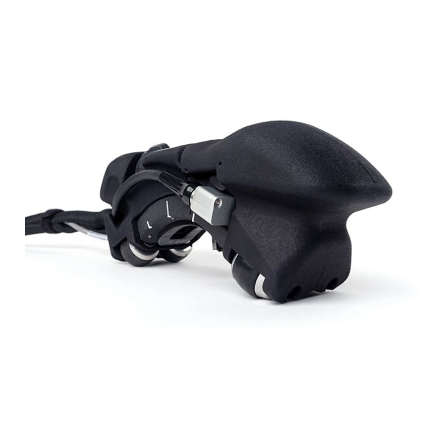
10-003591-01EN [Q7780031], Rev. 4, January 2020 Introduction The FlexoFORM scanner is designed to inspect pipes and pipe elbows. A flexible, phased array ultrasonic probe is held and shaped by a water wedge that is contoured to fit the radius of curvature of the surface being inspected. The scanner adjusts to hold wedges of various sizes for a range of radius of curvatures. - Page 26 10-003591-01EN [Q7780031], Rev. 4, January 2020 Introduction...
-
Page 27: Overview
The FlexoFORM scanner kits can be composed of different components. FlexoFORM Case Contents The FlexoFORM scanner case contents are shown in Figure 1-1 on page 19. Main components are detailed in Figure 1-2 on page 20. Spare parts kit (screws, o-rings, etc.), Allen... -
Page 28: Figure 1-2 Scanner Components
10-003591-01EN [Q7780031], Rev. 4, January 2020 WARNING The FlexoFORM scanner has magnetic wheels that must be carefully handled to prevent the risk of injury and equipment damage from magnetic fields and inadvertent attractive forces. Before unpacking and handling, observe the magnetic wheel safety precautions, as outlined in the warning note on page 27. -
Page 29: Alternative Components
10-003591-01EN [Q7780031], Rev. 4, January 2020 Alternative Components The FlexoFORM scanner requires dedicated SFA1-FLEXO series wedges and a FA1- type flexible probe. However, the FA1-type probe can also be used with two other wedge series designed to scan without a FlexoFORM scanner: •... - Page 30 10-003591-01EN [Q7780031], Rev. 4, January 2020 Chapter 1...
-
Page 31: Setup Of Equipment
10-003591-01EN [Q7780031], Rev. 4, January 2020 2. Setup of Equipment The FlexoFORM scanner and the instrument must be properly connected and set up to enable inspection. Setting Up an Instrument Using a USB Key You can load a predefined inspection-parameter setup from the supplied USB key into your OmniScan instrument. -
Page 32: Setup Characteristics
2.2.2 Setting the Parameters for a Symmetrical Scan For pipe elbow inspections, Olympus recommends the symmetrical scan pattern for a full 360° inspection around the circumference (see Figure 2-2 on page 25). The OmniScan instrument must be correctly set up to enable this type of inspection. For details about alternative inspection patterns for straight pipe surfaces, see “Setting Up... -
Page 33: Figure 2-2 Symmetrical Scan Pattern For A Pipe Elbow Inspection Of 360
LED. Because of its “smart indexing” function, the FlexoFORM scanner can then freely move along the index axis to the next scan line without overwriting any acquisition data. When the scanner is in position at the center of the next scan line (the zero position, or origin), the indexing button is pressed once again, and the red LED turns off. -
Page 34: Installing The Probe And Wedge
Because of its design, the flexible phased array probe can be easily damaged if handled incorrectly. It is not recommended to bring the probe into direct contact with a part. The probe should only be shaped using an Olympus SFA1 type wedge. Bending the probe too much could permanently damage it. -
Page 35: Figure 2-3 Installing The Probe And Wedge
• The wheels may suddenly attract ferromagnetic objects or particles in their vicinity, which can cause injury, equipment damage, or malfunction. Turn the thumb wheel to open the FlexoFORM scanner, and install the assembled wedge and probe. Setup of Equipment... -
Page 36: Connecting The Scanner
Connect the LEMO encoder cable to the OmniScan instrument (see Figure 2-4 on page 28). Connect the probe cable to the OmniScan instrument. Connect the water supply to an Olympus couplant feed unit. For more details on the recommended CFU03 pump connection, refer to the CFU03/CFU05/CFU-PWZ Couplant Feed Unit User’s Manual. -
Page 37: Preparation For Inspection
It is recommended that you also mark the scan lines. Drop Precautions Be sure to observe the following precautions when handling the FlexoFORM scanner. WARNING To prevent injury and equipment damage when operating the FlexoFORM scanner at heights 2 meters or higher above ground or floor level, secure it with a lanyard that is held taut (see attachment point in Figure 3-1 on page 30). -
Page 38: Cleaning The Inspection Surface
10-003591-01EN [Q7780031], Rev. 4, January 2020 Figure 3-1 Attachment point for lanyard IMPORTANT Olympus recommends that you keep the wedge securely mounted in the frame while handling the scanner. This provides increased resistance to accidental impact. Cleaning the Inspection Surface The inspection surface must be free of scaling and other obstructions. -
Page 39: Setting Up The Scan And Index Parameters For An Elbow
10-003591-01EN [Q7780031], Rev. 4, January 2020 To clean the inspection surface Carefully use an appropriate metal scraper, chisel, or file to remove scaling, protruding metal, or weld residue on the surface, without affecting the structural integrity and curvature of the surface. Use a metal brush to remove any remaining loose material on the surface. -
Page 40: Figure 3-3 Example Scan Start And Scan End Setting In The Omniscan
See Table 3 on page 42 to determine the effective beam width on the surface, and then subtract from it your desired scan overlap value. Because of the FlexoFORM scanner’s flexible, curved probe—with a radius of curvature that is concentric to the surface radius of curvature—the effective beam width on the surface is smaller than the Index Res value calculated by the OmniScan. -
Page 41: Marking The Scan Lines
Before an inspection, it is recommended that you lay out and mark scan lines to follow when moving the FlexoFORM scanner over a surface. The steps for determining the line length and spacing for an elbow are detailed in “Setting Up the Scan and Index Parameters for an Elbow”... -
Page 42: Figure 3-5 Marking The Zero Position (Left) And Scan (Right) Lines On An Elbow
Figure 3-5 Marking the zero position (left) and scan (right) lines on an elbow NOTE A template marking tool is provided with the FlexoFORM scanner package to help you draw scan lines. The supplied tool has markings that help you draw a line a distance of 48 mm to 58 mm from the previous line. -
Page 43: Figure 3-6 Drawing The Scan Lines On An Elbow
10-003591-01EN [Q7780031], Rev. 4, January 2020 Hole for paint marker Template marking tool and paint marker Scan line drawn by the paint marker Distance markings (in millimeters) Required indexing distance Figure 3-6 Drawing the scan lines on an elbow Preparation for Inspection... - Page 44 10-003591-01EN [Q7780031], Rev. 4, January 2020 Chapter 3...
-
Page 45: Inspection
To wet the surface and purge air bubbles Wet the surface, for example, by using a cloth soaked with water. Open the water supply, and then position the FlexoFORM scanner on the inspection surface. Move the scanner back and forth (and sideways, if necessary) over the inspection surface to help clear air bubbles. -
Page 46: Inspecting A Part
Use the following procedure if you have marked scan lines on your part surface. To inspect a part using marked scan lines Position the FlexoFORM scanner so that it is aligned with the (first) marked scan line and the start (zero) position (see Figure 4-2 on page 39). -
Page 47: Figure 4-2 Alignment Marks
On the OmniScan, press the Play key ( ) to set the encoder position to zero. Move the FlexoFORM scanner along the scan line, and observe the instrument display to make sure that all data has been captured. The recommended 360° scan pattern for a pipe (or pipe elbow) is shown in Figure 4-3 on page 40. -
Page 48: Inspecting A Part Without Marked Scan Lines
To inspect a part without marked scan lines Align the FlexoFORM scanner on the zero position (line around the pipe circumference) using the alignment marks on the sides, between the wheels. Use a pen to make a mark on the pipe at probe element 1 (see Figure 4-4 on page 41) and another mark at element 64. -
Page 49: Correction Factors
10-003591-01EN [Q7780031], Rev. 4, January 2020 Figure 4-4 Probe element marks on the wedge On the OmniScan, press the Play key ( ) to set the encoder position to zero. Make your scan motion, and observe the instrument display to make sure that all data has been captured. -
Page 50: Table 3 Effective Beam Width On Surface (Mm)
10-003591-01EN [Q7780031], Rev. 4, January 2020 Effective probe beam width Table 3 on page 42 provides corrected values for probe beam width for a range of pipe sizes and number of elements in focal laws. It is also possible to calculate the corrected value using equation (1) on page 43. The equation’s variables are illustrated in Figure 4-5 on page 43. -
Page 51: Figure 4-5 Variables For Calculating Probe Beam Width On The Surface
10-003591-01EN [Q7780031], Rev. 4, January 2020 A = Active aperture length B = Beam coverage width on the surface h = Water column height (9 mm for SFA1- FLEXO and SFA1-AUTO wedge series, and 11 mm for SFA1-SMALL wedge series) = Outside radius Figure 4-5 Variables for calculating probe beam width on the surface ------------------- -... -
Page 52: Table 4 Multiplication Factors For Defect Length Correction Along Index Axis
10-003591-01EN [Q7780031], Rev. 4, January 2020 Table 4 Multiplication factors for defect length correction along index axis Defect depth Pipe OD (in.) 2 mm 3 mm 4 mm 5 mm 6 mm 7 mm 8 mm 9 mm 10 mm 0.57 0.53 0.49... -
Page 53: Maintenance And Troubleshooting
Preventive Maintenance Because there are few moving parts, the FlexoFORM scanner does not require much preventive maintenance. Only regular inspection of the scanner is recommended to ensure that it is functioning correctly. If necessary, clean the scanner or clean and/or change the wheels, as outlined below. -
Page 54: Changing A Magnetic Wheel
2.1 m (7 ft) away from the wheels. This is well below the 2 milligauss limit at which a product would be considered to be a magnetic material requiring special handling during shipment by air. This means that the FlexoFORM scanner can be shipped by air without restrictions. - Page 55 IMPORTANT The FlexoFORM scanner’s replacement magnetic wheels are supplied as a set of two. The two wheels in a set have opposing polarity when installed. This provides a repulsive force between wheels that makes it easier to install them. However, wheels must be carefully handled and held to prevent accidental ejection, as outlined in the procedure below.
-
Page 56: Figure 5-1 Changing A Wheel
10-003591-01EN [Q7780031], Rev. 4, January 2020 To change a magnetic wheel CAUTION To avoid injury or equipment damage, be sure to carefully hold and restrict the movement of magnetic wheels when disassembling or assembling. The magnetic repulsive force between wheels may cause a wheel to suddenly eject if it is disassembled or assembled without an adequate hold. -
Page 57: Cleaning The Magnetic Wheels
10-003591-01EN [Q7780031], Rev. 4, January 2020 Cleaning the Magnetic Wheels The scanner and encoder’s magnetic wheels can attract sharp filings or other ferromagnetic objects or particles. The wheels need periodic cleaning to avoid accumulation of any particles that can cause injury or equipment malfunction. The cleaning frequency depends on your operating conditions. -
Page 58: Changing The Foam Gasket And The O-Ring Seals
Apply a small drop of Loctite 425 thread locker to each of the four screws, position the encoder, and insert and tighten the screws. Olympus recommends Loctite 425 thread locker because it will not damage plastic parts in the vicinity if inadvertently spilled. -
Page 59: Figure 5-3 Changing The Foam Gasket
10-003591-01EN [Q7780031], Rev. 4, January 2020 To change the foam gasket Pull off the old gasket, and, if necessary, carefully clean the mounting surface (see Figure 5-3 on page 51). Choose the gasket model that is compatible with the wedge diameter. Peel the backing off the adhesive on the new gasket. -
Page 60: Changing The Water Tube
10-003591-01EN [Q7780031], Rev. 4, January 2020 Figure 5-4 Changing the probe’s o-ring seal on the wedge To change the o-ring seal on the water connection Use an appropriate tool such as a small flathead screwdriver to carefully lift and pull off the old o-ring seal without damaging the mounting surface (see Figure 5-5 on page 52). -
Page 61: Changing The Cable Sleeve
10-003591-01EN [Q7780031], Rev. 4, January 2020 Feed the new tube through its channel on the scanner until it reaches the water connector. Push the tube onto the fitting, install the connector, and then tighten its screw. Cut the tube to the required length, connect it to the union connector, and then close the cable sleeve. - Page 62 10-003591-01EN [Q7780031], Rev. 4, January 2020 To change the cable sleeve Carefully remove the two wheels on the sleeve side according to the procedure detailed in “Changing a Magnetic Wheel” on page 46. Be aware of magnetic forces that can suddenly attract or repulse parts. Remove the screws that hold the scanner end piece, and pull it away.
-
Page 63: Troubleshooting
10-003591-01EN [Q7780031], Rev. 4, January 2020 Figure 5-7 Disassembly steps for changing the cable sleeve Troubleshooting Table 5 on page 56 lists some problems that may arise, possible causes, and suggested solutions. Maintenance and Troubleshooting... -
Page 64: Table 5 Troubleshooting Guide
Shut down the instrument and loaded. restart with correct software. No C-scan displayed. There is no encoder Check encoder connections connection. between FlexoFORM scanner and instrument. Black lines on C-scan. Scanning is too fast. Reduce scanning speed. Scanner does not open Mechanism contains... -
Page 65: Specifications
10-003591-01EN [Q7780031], Rev. 4, January 2020 6. Specifications General Specifications The general specifications for the FlexoFORM scanner are listed in Table 6 on page 57. Table 6 General specifications Parameter Value General Dimensions (L × W × H) 26 cm × 10 cm × 10 cm Weight 1.53 kg... -
Page 66: Wedge Pipe Diameter Ranges
IP55 Wedge Pipe Diameter Ranges The FlexoFORM scanner’s wedges have predefined curvatures according to the Nominal Pipe Size (NPS) standard. Although it is recommended to use a wedge that matches the exact diameter of the inspected pipe, each wedge has a narrow range of pipe diameters on which it can be used. -
Page 67: Table 7 Range Of Pipe Diameters Covered By Each Wedge
10-003591-01EN [Q7780031], Rev. 4, January 2020 Table 7 Range of pipe diameters covered by each wedge OD (in.) Min. OD (in.) Max. OD (in.) 5.563 6.625 8.625 10.75 10.3 11.1 11.75 11.1 12.1 12.75 12.1 13.3 13.1 14.6 14.9 16.8 16.6 18.9 18.4... -
Page 68: Flat Wedge Inspection Surfaces
10-003591-01EN [Q7780031], Rev. 4, January 2020 Flat Wedge Inspection Surfaces When fitted with a flat wedge, the FlexoFORM scanner can be used to perform these inspections on the following parts: • Flat plates • Circumferential inspection of pipes: — With 48 in. and up outside diameters —... -
Page 69: Dimensions
PHA-2 PHA-1 Green PHB-1 Orange Black 5 V IN Solder-side view FGG.0T.305.CLAC50Z Solder-side view FGG.1K.316.CLAC50Z Figure 6-1 LEMO connector pinout diagram (5 pin to 16 pin) Dimensions The FlexoFORM scanner dimensions are shown in Figure 6-2 on page 62. Specifications... -
Page 70: Figure 6-2 Scanner Dimensions
10-003591-01EN [Q7780031], Rev. 4, January 2020 98.2 mm (3.87 in.) 260.6 mm (10.26 in.) 100 mm (3.94 in.) 193 mm (7.6 in.) 93.1 mm (3.66 in.) 101.6 mm (4.00 in.) 52.5 mm 28.7 mm (2.07 in.) (1.13 in.) 38.9 mm (1.53 in.) Figure 6-2 Scanner dimensions The SFA1-SMALL wedge series dimensions and clearances are shown in Figure 6-3... -
Page 71: Figure 6-3 Sfa1-Small Wedge Clearances
10-003591-01EN [Q7780031], Rev. 4, January 2020 Length Circumferential clearance Height clearance Water side clearance Probe side clearance Pipe diameter Figure 6-3 SFA1-SMALL wedge clearances Specifications... -
Page 72: Figure 6-4 Sfa1-Small Wedge Width
10-003591-01EN [Q7780031], Rev. 4, January 2020 Width Figure 6-4 SFA1-SMALL wedge width Table 8 SFA1-SMALL wedge series dimensions and clearances Pipe diameter 1.315 1.66 2.375 2.875 (in. OD) Length (mm) 108.421 117.594 122.098 128.089 131.261 133.042 133.592 111.737 Circumfer- 160.537 170.563 176.208 185.836... -
Page 73: Spare Parts And Accessories
10-003591-01EN [Q7780031], Rev. 4, January 2020 7. Spare Parts and Accessories An exploded view of the FlexoFORM scanner is shown in Figure 7-1 on page 65. A list of standard spare parts is provided in Table 9 on page 66. Accessories and spare part kits are listed in Table 11 on page 70 to Table 14 on page 73. -
Page 74: Table 9 Spare Parts
Screw, M3 × 35 mm, hex head, stainless Q8301429 Name plate Q8301430 Shaft, threaded Q8301432 Wiper ring Q8301433 Encoder, FlexoFORM Q8301481 Encoder base, front Q8301482 Encoder base, back Q8301426 Lock washer, internal tooth, M2 Screw, M2 × 6 mm, hex head, stainless... - Page 75 OmniScan and FOCUS PX instruments. Cable and tube are 5 m long. Requires FA1 probe and SFA1 water wedges, which are ordered separately. Q8000207 N/A FlexoFORM encoder cable, 5 m long with LEMO FlexoFORM- connector compatible with current generation of SP-Cable OmniScan and FOCUS PX instruments Q7500064 N/A Basic spare part kit for FlexoFORM scanner —...
-
Page 76: Figure 7-2 Basic Spare Parts Kit (P/N: Q7500064)
10-003591-01EN [Q7780031], Rev. 4, January 2020 Table 9 Spare parts (continued) Part order Marketing Item Description number number Q8301466 N/A Allen key, 2 mm Q8301467 N/A Allen key, 1.5 mm Item included in spare parts kit (P/N: Q7500064) Figure 7-2 Basic spare parts kit (P/N: Q7500064) Figure 7-3 on page 69 shows an exploded view of the SFA1-AUTO and SFA1-SMALL wedges. -
Page 77: Figure 7-3 Sfa1-Auto And Sfa1-Small Wedges Exploded View
Q8301442 Kit of 10 o-ring seals for probe (on wedge) Q7500066 Kit of 12 foams for SFA1-AUTO FLEXOFORM-SP- water wedges. Compatible with LFOAM pipe diameters of 8.625 in. OD and Q7201701 Kit of ten (10) foams for SFA1- SFA1-SMALL-SP-Foam- SMALL-OD1.3 water wedge. -
Page 78: Table 11 Flexoform Scanner And Probe Kits
Requires FA1 probe and SFA1 water wedges, which are ordered separately. Q7500062 FlexoFORM scanner kit for corrosion inspection of pipe elbows. FlexoFORM Package includes: Flexible 7.5 MHz, 64 element FA1 phased array probe, one (1) SFA1 water wedge for 219 mm (8.625 in.) -
Page 79: Table 12 Flexoform Standard Wedges
Description number number Q7500063 FlexoFORM scanner kit for corrosion inspection of pipe elbows. FlexoFORM- Package includes: Flexible 7.5 MHz, 64 element FA1 phased array probe, six (6) SFA1 water wedges for 114 mm (4.5 in.), 168 mm (6.625 in.), 219 mm (8.625 in.), 273 mm (10.75 in.), 324 mm (12.75 in.), and 406 mm (16 in.) outside diameters,... -
Page 80: Table 13 Wedges For Automated Inspections
10-003591-01EN [Q7780031], Rev. 4, January 2020 Table 12 FlexoFORM standard wedges (continued) Part order Description Marketing number number Q7500078 As above, but for 610 mm (24 in.) pipe OD SFA1-Flexo-OD24 Q7500079 As above, but for 660 mm (26 in.) pipe OD... -
Page 81: Table 14 Wedges For Small-Diameter Pipes
The wedge also features an 11 mm high water column allowing inspection of up to 35 mm thick carbon steel materials. Compatible with the Mini-Wheel encoder. Not compatible with FlexoFORM scanner. Q7500107 As above, but for 42 mm (1.66 in.) pipe OD SFA1-Small-OD1.66... - Page 82 10-003591-01EN [Q7780031], Rev. 4, January 2020 Chapter 7...
-
Page 83: Appendix A: Setting Up To Inspect A Straight Pipe - Unidirectional Or Bidirectional Scan
10-003591-01EN [Q7780031], Rev. 4, January 2020 Appendix A: Setting Up to Inspect a Straight Pipe — Unidirectional or Bidirectional Scan Depending on your inspection needs, setup, and preferences, Olympus recommends the unidirectional or bidirectional scanning methods for straight pipe or cylinder surfaces. -
Page 84: Figure A-2 Bidirectional Scan Pattern
10-003591-01EN [Q7780031], Rev. 4, January 2020 To set up for a unidirectional scan Set the parameters as outlined in “To set the parameters for a symmetrical scan” on page 25. The setup and functionality are the same. Bidirectional scan The advantage of a bidirectional scan is that it is faster when inspecting long parts (see Figure A-2 on page 76). -
Page 85: Appendix B: Calculating True Defect Length
10-003591-01EN [Q7780031], Rev. 4, January 2020 Appendix B: Calculating True Defect Length To calculate the true defect length (Lo) along the index axis, use equation (2) on page 77. The variables are illustrated in Figure B-1 on page 77. = True defect length l = Measured defect length = Outside radius h = Water column height (9 mm for SFA1-FLEXO... - Page 86 10-003591-01EN [Q7780031], Rev. 4, January 2020 Appendix B...
-
Page 87: List Of Figures
10-003591-01EN [Q7780031], Rev. 4, January 2020 List of Figures Figure i-1 Labels location for scanner ................. 1 Figure i-2 FlexoFORM scanner ..................17 Figure 1-1 Case contents ...................... 19 Figure 1-2 Scanner components ..................20 Figure 1-3 Mini-Wheel encoder standard hardware kit ..........21 Figure 2-1 Selecting Plate in the Specimen Type field ............ - Page 88 10-003591-01EN [Q7780031], Rev. 4, January 2020 Figure 6-4 SFA1-SMALL wedge width ................64 Figure 7-1 Scanner exploded view ..................65 Figure 7-2 Basic spare parts kit (P/N: Q7500064) ............. 68 Figure 7-3 SFA1-AUTO and SFA1-SMALL wedges exploded view ......69 Figure A-1 Unidirectional scan pattern ................
-
Page 89: List Of Tables
Table 9 Spare parts ......................66 Table 10 SFA1 wedge spare part list ................... 69 Table 11 FlexoFORM scanner and probe kits ..............70 Table 12 FlexoFORM standard wedges ................71 Table 13 Wedges for automated inspections ..............72 Table 14 Wedges for small-diameter pipes ............... - Page 90 10-003591-01EN [Q7780031], Rev. 4, January 2020 List of Tables...
-
Page 91: Index
10-003591-01EN [Q7780031], Rev. 4, January 2020 Index CE 2 FCC (USA) 13 air bubbles 37 ICES-001 (Canada) 14 ancillary equipment 6 RCM (Australia) 2 Australia, RCM compliance 2 connection, scanner 28 connector pinout 60 bidirectional scan 76 correction factors 41 bubbles, air 37 DANGER signal word 8 cable sleeve 53... - Page 92 76 modification, industrial inspection system 6 lines 33 parameter setup 31 procedure 38 NOTE signal word 9 unidirectional 75 notes, information signal words 9 serial number format 3 setup installing probe and wedge 26 Olympus technical support 15 Index...
- Page 93 10-003591-01EN [Q7780031], Rev. 4, January 2020 loading an instrument setup 23 TIP signal word 9 parameters, pipe elbow 24 troubleshooting 55 scan and index parameters 31 scanner connections 28 unidirectional scan 75 signal words use, intended 5 information notes 9 IMPORTANT 9 NOTE 9 visual interference 7...
- Page 94 10-003591-01EN [Q7780031], Rev. 4, January 2020 Index...
Need help?
Do you have a question about the FlexoFORM and is the answer not in the manual?
Questions and answers