Table of Contents
Advertisement
Quick Links
ChainSCANNER
Chain-Link Mounted Scanner
User's Manual
This instruction manual contains essential information on how to use this Olympus product safely and effectively.
Before using this product, thoroughly review this instruction manual. Use the product as instructed.
Keep this instruction manual in a safe, accessible location.
DMTA069-01EN — Rev. D
March 2017
Advertisement
Chapters
Table of Contents

Related Manuals for Olympus ChainSCANNER


Summary of Contents for Olympus ChainSCANNER
- Page 1 DMTA069-01EN — Rev. D March 2017 This instruction manual contains essential information on how to use this Olympus product safely and effectively. Before using this product, thoroughly review this instruction manual. Use the product as instructed. Keep this instruction manual in a safe, accessible location.
- Page 2 Olympus Scientific Solutions Americas, 48 Woerd Avenue, Waltham, MA 02453, USA Copyright © 2009, 2014, 2017 by Olympus. All rights reserved. No part of this publication may be reproduced, translated, or distributed without the express written permission of Olympus. This document was prepared with particular attention to usage to ensure the accuracy of the information contained therein, and corresponds to the version of the product manufactured prior to the date appearing on the title page.
-
Page 3: Table Of Contents
DMTA069-01EN, Rev. D, March 2017 Table of Contents List of Abbreviations ..................vii Labels and Symbols ................... 1 Important Information — Please Read Before Use ........3 Intended Use .......................... 3 Instruction Manual ........................ 3 Instrument Compatibility ..................... 4 Presence of Visual Interferences or Phantom Spots ............5 Safety Symbols ........................ - Page 4 Optional Four-Probe Kit ..................40 Optional Mouse Conversion Kit ................42 2.10 Optional 20-Centimeter Bar and Lead Screw Kit ..........46 3. Preparing the ChainSCANNER for an Inspection ......49 4. Operating the ChainSCANNER .............. 53 5. Maintenance ....................55 Preventive Maintenance ...................
- Page 5 DMTA069-01EN, Rev. D, March 2017 Index ........................87 Table of Contents...
- Page 6 DMTA069-01EN, Rev. D, March 2017 Table of Contents...
-
Page 7: List Of Abbreviations
DMTA069-01EN, Rev. D, March 2017 List of Abbreviations Communauté Européenne (European Community) not applicable outside diameter part number TOFD time-of-flight diffraction WEEE Waste Electrical and Electronic Equipment List of Abbreviations... - Page 8 DMTA069-01EN, Rev. D, March 2017 viii List of Abbreviations...
-
Page 9: Labels And Symbols
Marking locations on the instrument are shown in Figure i-1 on page 1. If any or all of the labels or symbols are missing or illegible, please contact Olympus. The descriptions of the symbols are provided in Table 1 on page 2. -
Page 10: Table 1 Symbols
The CE marking is a declaration that this product conforms to all the applicable directives of the European Community. See the Declaration of Conformity for details. Contact your Olympus representative for more information. The WEEE symbol indicates that the product must not be disposed of as unsorted municipal waste, but should be collected separately. -
Page 11: Important Information - Please Read Before Use
ChainSCANNER allows encoding on the two axes—the x-axis encoder and the y-axis encoder. WARNING Do not use the ChainSCANNER for any purpose other than its intended use. It must never be used to inspect or examine human or animal body parts. Instruction Manual This instruction manual contains essential information on how to use this Olympus product safely and effectively. -
Page 12: Instrument Compatibility
The images in this manual may not be identical to your instrument model and connector type. However, the operating principles remain the same. Instrument Compatibility The ChainSCANNER is compatible with the Olympus ancillary equipment listed in Table 2 on page 4. Table 2 Ancillary equipment... -
Page 13: Presence Of Visual Interferences Or Phantom Spots
DMTA069-01EN, Rev. D, March 2017 CAUTION Always use equipment and accessories that meet Olympus specifications. Using incompatible equipment could cause equipment malfunction and/or damage, or human injury. Presence of Visual Interferences or Phantom Spots IMPORTANT In a situation of physical proximity of powerful electromagnetic radiators, visual interferences or phantom spots maybe present. -
Page 14: Safety Signal Words
DMTA069-01EN, Rev. D, March 2017 Safety Signal Words The following safety symbols might appear in the documentation of the instrument: DANGER The DANGER signal word indicates an imminently hazardous situation. It calls attention to a procedure, practice, or the like that if not correctly performed or adhered to will result in death or serious personal injury. -
Page 15: Safety
DMTA069-01EN, Rev. D, March 2017 NOTE The NOTE signal word calls attention to an operating procedure, practice, or the like, which requires special attention. A note also denotes related parenthetical information that is useful, but not imperative. The TIP signal word calls attention to a type of note that helps you apply the techniques and procedures described in the manual to your specific needs, or provides hints on how to effectively use the capabilities of the product. -
Page 16: Ce (European Community)
This equipment generates and uses radio-frequency energy and, if not installed and used properly (that is, in strict accordance with the manufacturer’s instructions), may cause interference. The ChainSCANNER has been tested and found to comply with the limits for an industrial device in accordance with the specifications of the EMC directive. -
Page 17: Warranty Information
Retain packing materials, waybills, and other shipping documentation needed in order to file a damage claim. After notifying the carrier, contact Olympus for assistance with the damage claim and equipment replacement, if necessary. - Page 18 DMTA069-01EN, Rev. D, March 2017 Important Information — Please Read Before Use...
-
Page 19: Introduction
Introduction This manual provides instructions for assembling, installing, and operating the ChainSCANNER. The ChainSCANNER is a manual pipe inspection scanner for outside pipe diameters ranging from 45 mm to 965 mm (1.75 in. to 38 in.). The ChainSCANNER allows encoding the position on the two axes. - Page 20 DMTA069-01EN, Rev. D, March 2017 Introduction...
-
Page 21: Overview
DMTA069-01EN, Rev. D, March 2017 1. Overview This chapter provides an overview of the ChainSCANNER components in the standard configuration. The scanner is shown in Figure 1-1 on page 13. A description of each component follows. Probe-holder assembly (wedge and probe not... -
Page 22: Slide Bar Assembly
DMTA069-01EN, Rev. D, March 2017 Slide Bar Assembly The slide bar holds most of the components of the ChainSCANNER, and permits easy and precise positioning of the probe-holder assemblies (see Figure 1-2 on page 14). Thumb knobs (2) Large knob... -
Page 23: Probe-Holder Assembly
DMTA069-01EN, Rev. D, March 2017 Probe Slide bar displacement system Figure 1-3 The probe displacement system Probe-Holder Assembly The probe-holder assembly is designed to hold a wedge-probe assembly and to ensure contact between the wedge and the surface (see Figure 1-4 on page 16). Overview... -
Page 24: Buckle Assembly
(see “To change the yoke arms” on page 33). Buckle Assembly The purpose of the buckle assembly is to attach the ChainSCANNER and to adjust the tension around the pipe (see Figure 1-5 on page 17). For extra-small Chapter 1... -
Page 25: Main Module And Encoder Umbilical Cable
Figure 1-5 The buckle assembly parts Main Module and Encoder Umbilical Cable The main module of the ChainSCANNER offers an ergonomic grip to manipulate the scanner (see Figure 1-7 on page 18). The main module also holds an internal x-axis encoder and its connector. The umbilical encoder cable connects to the x-axis connector and provides the y-axis encoder connector (see Figure 1-6 on page 17). -
Page 26: Y-Axis Encoder
DMTA069-01EN, Rev. D, March 2017 Ergonomic cover Removable knob Encoder umbilical Encoder cable-release umbilical wing knob cable X-axis encoder wheel Figure 1-7 The main module components Y-Axis Encoder The y-axis encoder measures the probe holders displacement on the lateral axis (see Figure 1-8 on page 18). -
Page 27: Short And Long Links
Figure 1-9 The short and long links NOTE The ChainSCANNER is not recommended for pipes larger than 965 mm (38 in.) OD, because on pipes above this diameter, the scanner tends to make ellipsoidal rotations, which makes it difficult to align the probes with the weld. - Page 28 DMTA069-01EN, Rev. D, March 2017 Chapter 1...
-
Page 29: Chainscanner Setup And Connection
This section gives the procedures used to configure the main module in order to use it as a component of the ChainSCANNER. To use the main module in the mouse scanner configuration, the optional mouse conversion kit is required, see “Optional Mouse Conversion Kit”... -
Page 30: Figure 2-1 Coupling The Main Module With The Slide Bar
DMTA069-01EN, Rev. D, March 2017 To couple the main module and the slide bar Removable knob Slide bar Dovetail groove Split dovetail Supplied tool Figure 2-1 Coupling the main module with the slide bar If there is enough room to manipulate the removable knob, use it to couple the main module to the slide bar. -
Page 31: Figure 2-2 Collapsing And Opening A Split Dovetail
(see Figure 2-2 on page 23). Turn the knob Turn the knob counterclockwise clockwise to to open the split collapse the split dovetail. dovetail. Opened split Collapsed split dovetail dovetail Figure 2-2 Collapsing and opening a split dovetail ChainSCANNER Setup and Connection... -
Page 32: Figure 2-3 Removing The Ergonomic Cover
DMTA069-01EN, Rev. D, March 2017 To remove the ergonomic cover Remove the removable knob. Slide the cover 13 mm forward and lift. Figure 2-3 Removing the ergonomic cover Pull out the removable knob if required (see Figure 2-3 on page 24). Hold the metallic body of the main module. -
Page 33: Figure 2-4 The Main Module Without The Encoder Umbilical Cable
To connect the y-axis encoder cable Remove the ergonomic cover (see “To remove the ergonomic cover” on page 24). Cable management tabs Encoder umbilical cable Y-axis encoder connector Figure 2-5 The encoder connector and the cable management tabs. ChainSCANNER Setup and Connection... -
Page 34: Chainscanner Setup
To add or remove a link on the ChainSCANNER Measure the outside diameter or the circumference of the pipe to be inspected. -
Page 35: Probe Holders Adjustment And Maintenance
Attach this link assembly to the front and rear attachments of the main module. Probe Holders Adjustment and Maintenance The ChainSCANNER can hold a pair of conventional UT probes or a pair of phased array probes. The probes are mounted on probe holders (see Figure 2-7 on page 28) that need the following types of adjustments: •... -
Page 36: Figure 2-7 Probe-Holder Assembly Parts
DMTA069-01EN, Rev. D, March 2017 Yoke Removable knob Swing arm Split dovetail Wing knob Latch knob Pivot buttons (2) Mobile yoke arm Figure 2-7 Probe-holder assembly parts Removable knob The removable knob mounted on the swing arm allows for a precise positioning of the probe holder along the slide assembly or the slide bar (see Figure 2-7 on page 28). - Page 37 Slide the mobile yoke arm to accept the wedge-probe assembly so that the pivot buttons engage in the wedge holes. Tighten the wing knob. To install the probe holder onto the ChainSCANNER Collapse the split dovetail by rotating the removable knob clockwise. Insert the probe holder assembly directly into the scanner’s dovetail groove.
-
Page 38: Figure 2-8 Collapsing And Opening A Split Dovetail
DMTA069-01EN, Rev. D, March 2017 Once the split dovetail is collapsed, it can be inserted anywhere along the dovetail groove. Turn the knob Turn the knob counterclockwise clockwise to to open the split collapse the split dovetail. dovetail. Open split Collapsed split dovetail dovetail... -
Page 39: Figure 2-10 Adjusting The Distance Between The Probes
Loosen the thumb knob on the slide assembly that you wish to adjust (see Figure 2-10 on page 31). Turn the small knob on the slide assembly while holding the large knob to prevent it from rotating. Tighten the thumb knob. ChainSCANNER Setup and Connection... -
Page 40: Changing The Yoke Arm To Fit The Length Of A Wedge
Ensure that the thumb-knobs, the lock screw, and the large knob are tight. Attach the probe holders to the slide assembly (see “To install the probe holder onto the ChainSCANNER” on page 29). Rotate the large knob to adjust the position of the pair of probes (see Figure 2-11 on page 32). -
Page 41: Figure 2-12 Changing The Yoke Arms
Install the wedge-probe assembly (see “To install the wedge-probe assembly to the probe holder” on page 29). Install the new mobile yoke arm and tighten the wing knob. 10. Ensure that the wedge-probe assembly is centered with the yoke pivot. ChainSCANNER Setup and Connection... -
Page 42: Slide Bar, Lead Screw, And Y-Axis Adjustment
DMTA069-01EN, Rev. D, March 2017 Slide Bar, Lead Screw, and Y-Axis Adjustment To replace the slide bar and the lead screw If an encoder assembly is present, remove it (see “To remove the y-axis encoder” on page 35). Loosen the hexagonal screw on the large knob two turns. Loosen the lock screw. -
Page 43: Y-Axis Encoder Removal And Installation
Tighten the lock screw with a hexagonal key (see Figure 2-14 on page 35). Y-Axis Encoder Removal and Installation The ChainSCANNER comes equipped with a y-axis encoder. If required, the y-axis encoder can be removed or installed. To remove the y-axis encoder To remove, loosen the lock screw. -
Page 44: Umbilical Sheath Strain Relief Assembly
(see Figure 2-15 on page 36). Tighten the lock screw. Umbilical Sheath Strain Relief Assembly The umbilical cable must be attached to the ChainSCANNER. To assemble the umbilical cable sheath Slide the annular part of the strain relief over the cable sheath, as shown in Figure 2-16 on page 37. -
Page 45: Figure 2-16 Sliding Annular Part Of The Relief Connector Over The Cable Sheath
Figure 2-17 Inserting the threaded portion of the strain relief into the cable sheath Put the cable sheath sections back together. Align and assemble the threaded and annular parts of the strain relief (see Figure 2-18 on page 38). ChainSCANNER Setup and Connection... -
Page 46: Figure 2-18 Assembling The Strain Relief Connector
Connect the LEMO connector of the umbilical cable to the main module of the ChainSCANNER (see Figure 2-19 on page 38). Figure 2-19 Connecting the umbilical cable to the ChainSCANNER’s main module Attach the umbilical cable to the ChainSCANNER using the thumb screw (see Figure 2-20 on page 39). Chapter 2... -
Page 47: Figure 2-20 Attaching The Umbilical Cable To The Chainscanner
DMTA069-01EN, Rev. D, March 2017 Figure 2-20 Attaching the umbilical cable to the ChainSCANNER The procedure is now complete (see Figure 2-21 on page 40). ChainSCANNER Setup and Connection... -
Page 48: Optional Four-Probe Kit
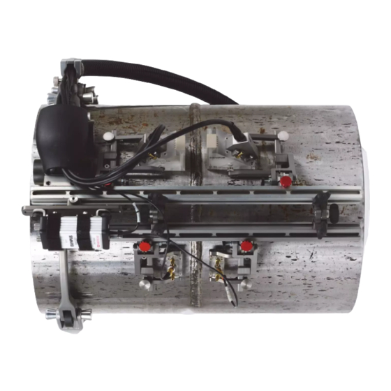
DMTA069-01EN, Rev. D, March 2017 Umbilical sheath strain relief assembly Figure 2-21 The ChainSCANNER with four-probe kit installed Optional Four-Probe Kit The optional four-probe kit (P/N: CHAINSCAN-A-4PROBE [U8775128]) allows the use of four probes on large pipes. The four-probe assembly adapts to the pipe circumference through the pivots of the additional frame bar pivots (see Figure 2-22 on page 41). -
Page 49: Figure 2-22 The Optional Four-Probe Kit
DMTA069-01EN, Rev. D, March 2017 Pre-amplifier mounting bracket Additional bar (1) Frame bar pivots (2) Additional probe holders (2) Figure 2-22 The optional four-probe kit For an example of the ChainSCANNER, four-probe configuration, see Figure 2-23 on page 42). ChainSCANNER Setup and Connection... -
Page 50: Optional Mouse Conversion Kit
Figure 2-23 The ChainSCANNER, four-probe configuration Optional Mouse Conversion Kit The main module of the ChainSCANNER can be used as a mouse scanner, that is to say, without the chain components. This option allows the scanner to be held against a ferromagnetic surface by a set of magnetic wheels instead of by the chain component. -
Page 51: Figure 2-24 The Optional Mouse Conversion Kit
Remove the main module assembly from the slide bar (see “To couple the main module and the slide bar” on page 22). For an easier manipulation, remove the encoder umbilical cable from the main module (see “To install or release the encoder umbilical cable” on page 24). ChainSCANNER Setup and Connection... -
Page 52: Figure 2-25 The Main Module Equipped With The Chain Attachment
DMTA069-01EN, Rev. D, March 2017 Rear screw Rear attachment for chain links Wheel screw Front screw Standard non magnetic wheels Front attachment for chain links Figure 2-25 The main module equipped with the chain attachment Use a hexagonal key or the supplied universal tool to unscrew the front screw securing the mouse front attachment for chain links (see Figure 2-25 on page 44). -
Page 53: Figure 2-26 Mouse-Dedicated Dovetail Front Attachment And Parking Brake
Install the magnetic wheels using the hexagonal key or the supplied universal tool to secure it in place (see Figure 2-28 on page 46). 10. Reverse the procedure to transform the mouse scanner back into the ChainSCANNER configuration. ChainSCANNER Setup and Connection... -
Page 54: 2.10 Optional 20-Centimeter Bar And Lead Screw Kit
DMTA069-01EN, Rev. D, March 2017 Figure 2-28 Magnetic wheels to hold the mouse scanner on ferromagnetic surface 2.10 Optional 20-Centimeter Bar and Lead Screw Kit The 20-centimeter bar and lead-screw kit (P/N: CHAINSCAN-A-SBAR [U8775129]) allows for a very compact configuration of the scanner. It can be used with the mouse conversion kit (P/N: CHAINSCAN-A-MOUSE [U8750037]) as shown in Figure 2-29 on page 47, as well as a with the chain assembly (see Figure 2-30 on page 48). -
Page 55: Figure 2-29 The 20-Centimeter Bar And Lead Screw Option-Mouse Scanner
To use the y-axis adjustment on the 20 cm slide bar, retrieve the large red knob assembly and one of the two small red knob assemblies from the ChainSCANNER standard configuration (see “To replace the slide bar and the lead screw” on page 34) and use the 20 cm lead screw instead of the standard lead screw. -
Page 56: Figure 2-30 The 20-Centimeter Bar And Lead-Screw Option-Chainscanner
DMTA069-01EN, Rev. D, March 2017 Figure 2-30 The 20-centimeter bar and lead-screw option—ChainSCANNER Chapter 2... -
Page 57: Preparing The Chainscanner For An Inspection
Engage the buckle latch to close the ChainSCANNER around the pipe. CAUTION Extreme over-tensioning can reduce the life of the buckle components. CAUTION When the inspection is finished, release the tension on the ChainSCANNER to avoid flattening of the rubber wheels. Preparing the ChainSCANNER for an Inspection... -
Page 58: Figure 3-1 Closing The Chain Around The Pipe
Figure 3-1 Closing the chain around the pipe When preparing the ChainSCANNER for larger diameter pipes, the scanner’s position must be adjusted, to avoid helicoidal movement as much as possible. Otherwise, go directly to step 8. For larger diameter pipes, adjust the scanner’s position. Do the following: a) Measure the distance between the side of the wheel of the module and the weld (for example, 100 mm). -
Page 59: Figure 3-2 Cables Passing Underneath The Module's Ergonomic Cover (Model Equipped With Four-Probe Kit Shown)
Ergonomic cover Scanner cables passing underneath cover Figure 3-2 Cables passing underneath the module’s ergonomic cover (model equipped with Four-Probe kit shown) 11. Cover the cables and tubes with the supplied divisible cable protection. Preparing the ChainSCANNER for an Inspection... - Page 60 DMTA069-01EN, Rev. D, March 2017 12. Attach the divisible cable protection to the chain to avoid excessive stress on the cables and tubes connections (see “Umbilical Sheath Strain Relief Assembly” on page 36). Chapter 3...
-
Page 61: Operating The Chainscanner
DMTA069-01EN, Rev. D, March 2017 4. Operating the ChainSCANNER The ChainSCANNER is designed to be used manually. It is simple to operate. To operate the ChainSCANNER Fasten the scanner around the pipe to be inspected (see “To prepare the ChainSCANNER for an inspection” on page 49). - Page 62 DMTA069-01EN, Rev. D, March 2017 IMPORTANT All wedge-probe assemblies must be correctly positioned on the surface being inspected. IMPORTANT All carbide wear-pins should be flush with the wedge surface (see Appendix B, “Wedge-Probe Assembly Maintenance” on page 77). IMPORTANT For proper contact between the wedge and the part being inspected when performing an inspection, always make sure that the swing arm is unlatched.
-
Page 63: Maintenance
Preventive Maintenance The ChainSCANNER does not require preventive maintenance. Only a regular inspection of the product is recommended to ensure that the ChainSCANNER functions correctly. Unit Cleaning The ChainSCANNER external surfaces can be cleaned when needed. This section provides the procedure for the appropriate cleaning of the product. - Page 64 DMTA069-01EN, Rev. D, March 2017 Chapter 5...
-
Page 65: Spare Parts And Optional Kits
Individual spare parts and parts kits are listed in tables. Spare Parts An exploded view and a list of spare parts for the ChainSCANNER are provided in Figure 6-1 on page 58 and Table 3 on page 58 for the frame and chain, and in Figure 6-2 on page 61 and Table 4 on page 62 for the cart. -
Page 66: Figure 6-1 Chainscanner Frame And Chain - Exploded View
Note: Items 33–38 are for legacy (old) encoders with serial numbers 128982 and lower. Item 11 is the new encoder; serial numbers 128983 and higher. Figure 6-1 ChainSCANNER frame and chain — exploded view Table 3 ChainSCANNER spare parts — frame and chain Drawing Part... - Page 67 Main large red knob for y-axis indexation on MAINKNOB ChainSCANNER. Features mounting holes for crank handle installation. U8775146 CHAINSCAN-A- ChainSCANNER 38 cm lead screw to be used on the XY LSCREW38 option with the longitudinal “Y” encoder U8830732 CHAINSCAN-A- Probe-holder bar, 450 mm dovetail slide...
- Page 68 DMTA069-01EN, Rev. D, March 2017 Table 3 ChainSCANNER spare parts — frame and chain (continued) Drawing Part Marketing number Description item number 17+18+19 U8775262 CHAINSCAN-A- Slim, 63.5 mm long arm sets for ChainSCANNER with ARM-SPA 8 mm buttons for PA probe.
-
Page 69: Figure 6-2 Chainscanner Cart - Exploded View
DMTA069-01EN, Rev. D, March 2017 Table 3 ChainSCANNER spare parts — frame and chain (continued) Drawing Part Marketing number Description item number U8775145 CHAINSCAN-SP- Legacy (old) encoder assembly for longitudinal “Y” axis. Resolution: 1024 counts/revolution NOTE: Only for encoder serial numbers 128982 and lower. -
Page 70: Optional Kits And Parts
U8775205 CHAINSCAN-A- Crank handle for y-axis indexation on CRANK ChainSCANNERs. NOTE: Will only fit if the main red knob of the ChainSCANNER has the mounting holes. If not, a knob (P/N: CHAINSCAN-A-MAINKNOB [U8775206]) must also be ordered. Chapter 6... - Page 71 DMTA069-01EN, Rev. D, March 2017 Table 5 ChainSCANNER optional kits and parts (continued) Part Marketing Part or kit image Description number number U8779370 CHAINSCAN-SP- Basic spare parts kit for the ChainSCANNER BASIC including: Lead screw and lever for buckle, wedge...
- Page 72 Marketing Part or kit image Description number number U8775190 CHAINSCAN-A- Bracket to pivot a ChainSCANNER yoke from 0° to TRANSVERS 90° U8775196 CHAINSCAN-A- Swivel nose to be installed on the front of a SWNOSE ChainSCANNER. Suitable for holding one probe holder bar and allowing rotation along the long axis of the bar.
- Page 73 DMTA069-01EN, Rev. D, March 2017 Table 5 ChainSCANNER optional kits and parts (continued) Part Marketing Part or kit image Description number number U8775114 TRPP-5810-INST Ultrasonic pulser and preamplifier kit dedicated for TOFD applications. Can support one or two pairs of TOFD probes.
- Page 74 DMTA069-01EN, Rev. D, March 2017 Chapter 6...
-
Page 75: Chainscanner Specifications
DMTA069-01EN, Rev. D, March 2017 7. ChainSCANNER Specifications This chapter contains the specifications for the ChainSCANNER. General and Operating Environment Specifications Table 6 General specifications Parameter Value Pipe range outside diameter 45 mm (1.75 in.) to 965 mm (38 in.) Main module dimension 7.5 cm ×... -
Page 76: Connector Reference
DMTA069-01EN, Rev. D, March 2017 Table 7 Operating environment specifications Parameter Value Operating temperature 5 °C to 50 °C (41 °F to 122 °F) Storage temperature ‒30 °C to 60 °C (‒22 °F to 140 °F) Relative humidity (RH) Max. 80 % RH noncondensing Wet location Altitude Up to 2000 m... -
Page 77: Figure 7-1 Lemo Connector Pinout Diagram
+5 V External power supply PhA axis 1 Encoder 1: phase A PhB axis 1 Encoder 1: phase B PhB axis 2 Encoder 2: phase B PhA axis 2 Encoder 2: phase A Ground Case Shield Ground earthing ChainSCANNER Specifications... - Page 78 DMTA069-01EN, Rev. D, March 2017 Chapter 7...
-
Page 79: Appendix A: Chainscanner Sizing Charts
DMTA069-01EN, Rev. D, March 2017 Appendix A: ChainSCANNER Sizing Charts The following ChainSCANNER sizing tables are a reference to determine an appropriate number of links for a given pipe size. There is a metric chart and a U.S. Customary unit chart. Each cell in the chart shows a range of pipe outside diameters—pipe circumferences are between parenthesis. -
Page 80: Table 10 Chainscanner Sizing Chart (Inches)
DMTA069-01EN, Rev. D, March 2017 Table 10 ChainSCANNER sizing chart (inches) Number of short links (Ordering number: ChainScan-A-SLink) 3.4–4.4 (10.8–13.9) 4.3–5.3 (13.6–16.7) 5.2-6.2 (16.2–19.3) 1.6–3.5 (5.1–11.0) 9.6–9.9 (30.2–31.0) 9.8–10.6 (30.7–33.4) 10.5–11.4 (33.1–35.8) 9.9–10.8 (31.2–33.8) 10.7–11.5 (33.6–36.1) 11.4–12.3 (35.9–38.5) 12.2–13.0 (38.2–40.9) 12.9–13.8 (40.6–43.4) - Page 81 21 56.5–57.5 (177.6–180.7) 57.3–58.3 (180.1–183.2) 58.1–59.1 (182.6–185.7) 58.9–59.9 (185.1–188.2) 59.7–60.7 (187.6–190.7) 22 58.9–59.9 (185.1–188.2) 59.7–60.7 (187.6–190.7) 60.5–61.5 (190.1–193.2) 61.3–62.3 (192.6–195.7) 62.1–63.1 (195.1–198.2) 23 61.3–62.3 (192.7–195.7) 62.1–63.1 (195.1–198.2) 62.9–63.9 (197.6–200.7) 63.7–64.7 (200.1–203.2) 64.5–65.5 (202.6–205.8) 24 63.7–64.7 (200.1–203.2) 64.5–65.5 (202.6–205.7) 65.3–66.3 (205.1–208.2) 66.1–67.1 (207.6–210.7) 66.9–67.9 (210.1–213.2) ChainSCANNER Sizing Charts...
-
Page 82: Table 11 Chainscanner Sizing Chart (Centimeters)
DMTA069-01EN, Rev. D, March 2017 Table 11 ChainSCANNER sizing chart (centimeters) Number of short links (Ordering number: ChainScan-A-SLink) 8.8–11.2 (27.5–35.3) 11.0–13.5 (34.5–42.3) 13.1–15.6 (41.2–49.1) 4.1–8.9 (13.0–28.0 24.5–25.1 (76.8–78.7) 24.8–27.0 (78.1–84.8) 26.7–28.9 (84.0–90.9) 25.3–27.3 (79.3–85.8) 27.1–29.2 (85.3–91.8) 29.0–31.1 (91.1–97.8) 30.9–33.1 (97.0–103.9) 32.8–35.1 (103.1–110.1) - Page 83 21 143.6–146.1 (451.1–459.0) 145.6–148.2 (457.5–465.4) 147.7–150.1 (463.9–471.7) 149.7–152.2 (470.2–478.0) 151.7–154.2 (476.6–484.5) 22 149.7–152.2 (470.2–478.1) 151.7–154.2 (476.5–484.4) 153.7–156.2 (482.9–490.7) 155.7–158.2 (489.3–497.2) 157.8–160.3 (495.6–503.5) 23 155.8–158.2 (489.4–497.1) 157.8–160.3 (495.6–503.5) 159.8–162.3 (501.9–509.8) 161.8–164.3 (508.3–516.2) 163.8–166.4 (514.6–522.7) 24 161.8–164.3 (508.3–516.2) 163.8–166.3 (514.6–522.5) 165.8–168.3 (521.0–528.9) 167.8–170.4 (527.3–535.3) 169.9–172.4 (533.7–541.6) ChainSCANNER Sizing Charts...
- Page 84 DMTA069-01EN, Rev. D, March 2017 Appendix A...
-
Page 85: Appendix B: Wedge-Probe Assembly Maintenance
DMTA069-01EN, Rev. D, March 2017 Appendix B: Wedge-Probe Assembly Maintenance The following procedures are not specific to the ChainSCANNER. They are nevertheless useful information to complete this manual. Adjustment of the Carbide Wear-Pins on Wedges Wedges are designed to hold a transducer or a phased array probe in order to ensure an adequate ultrasonic diffusion through the surface being inspected, and to direct the couplant flow correctly. -
Page 86: Replacing A Conventional Ultrasonic Transducer
DMTA069-01EN, Rev. D, March 2017 Top view Bottom view Carbide wear pins Use a hexagonal key to adjust the height of the carbide wear pins. The carbide wear pins must be flush with the surface of the wedge. Figure 7-2 Adjusting the wedge’s carbide wear pins To adjust the carbide wear-pins on a wedge Turn off the couplant flow. - Page 87 DMTA069-01EN, Rev. D, March 2017 To replace a conventional ultrasonic transducer Turn off the couplant flow. Disconnect the couplant tubes from the couplant source, or from the wedge. Remove the scanner from the inspection surface. Disconnect the transducer cable. Lift the swing arm until the latch engages into its higher position (see “To latch the swing arm”...
-
Page 88: Replacing A Phased Array Probe
DMTA069-01EN, Rev. D, March 2017 Replacing a Phased Array Probe To replace a phased array ultrasonic probe, the probe assembly must be removed and partially disassembled. To replace a phased array probe Turn off the couplant flow. Disconnect the couplant tubes from the couplant source. Disconnect the probe cable from the instrument. -
Page 89: Figure 7-3 The Wing Knob Holding The Mobile Yoke Arm
DMTA069-01EN, Rev. D, March 2017 Turn the wing knob counterclockwise to free the mobile yoke arm. Figure 7-3 The wing knob holding the mobile yoke arm Use the wing knob to free the mobile yoke arm that holds the yoke parts together (see Figure 7-3 on page 81). - Page 90 DMTA069-01EN, Rev. D, March 2017 CAUTION Do not overtighten the screws: overtightening might crack the wedge. 10. Reinstall the wedge-probe assembly on the yoke. 11. Lift the swing arm slightly. 12. Pull out the latch knob. 13. Release the swing arm slowly to its lower position (see “To unlatch the swing arm”...
-
Page 91: List Of Figures
Inserting the threaded portion of the strain relief into the cable sheath ... 37 Figure 2-18 Assembling the strain relief connector ............38 Figure 2-19 Connecting the umbilical cable to the ChainSCANNER’s main module . 38 Figure 2-20 Attaching the umbilical cable to the ChainSCANNER ........ 39 List of Figures... - Page 92 (model equipped with Four-Probe kit shown) ..........51 Figure 4-1 Center the inspection area between the probes ..........53 Figure 6-1 ChainSCANNER frame and chain — exploded view ........58 Figure 6-2 ChainSCANNER cart — exploded view ............61 Figure 7-1 LEMO connector pinout diagram ..............
-
Page 93: List Of Tables
Table 1 Symbols ........................2 Table 2 Ancillary equipment ....................4 Table 3 ChainSCANNER spare parts — frame and chain ..........58 Table 4 ChainSCANNER spare parts — cart ..............62 Table 5 ChainSCANNER optional kits and parts ............62 Table 6 General specifications ................... - Page 94 DMTA069-01EN, Rev. D, March 2017 List of Tables...
- Page 95 19 20 cm bar 40 chart (centimeters) 74 additional 40 chart (inches) 72 buckle assembly tension, caution 49 buckle arm 17 ChainSCANNER catch link 17 compatibility 4 definition 16 components 13 latch 17 buckle arm 17 position 26 buckle assembly 13, 16...
- Page 96 30 centimeters 74 slide bar 30 inches 72 split ~ 22 cleaning the unit 55 compatible equipment caution 5 EMC directive compliance 8 ChainSCANNER 4 encoder compliance connector 26 EMC directive 8 wheel 18 RCM (Australia) 2 x-axis 17 components...
- Page 97 19 pivot 40, 41 short and long 19 general specifications 67 magnetic wheels 42 groove, dovetail 22, 30 main components See ChainSCANNER: com- ponents main module handles, installing at intervals 26 description 17 hexagonal screw 33 cable management tabs 25...
-
Page 98: Table 7 Operating Environment Specifications
7 preparation, ChainSCANNER 49 Olympus technical support 9 preventive maintenance 55 operating environment specifications 67 probe (type) operation, ChainSCANNER 53, 54 conventional (replacement) 78 options phased array (replacement) 80 20-centimeter bar and lead screw kit 46 probe displacement system... - Page 99 DMTA069-01EN, Rev. D, March 2017 resolution latch 28 x-axis encoder 67 unlatching during inspection 29, 54 y-axis encoder 67 yoke 33 rubber wheels, caution 49 symbols 1 CE 2 direct current 2 safety RCM (Australia) 2 instrument compatibility 5 safety 5 misuse of instrument 3 warning 2 precautions 7...
- Page 100 DMTA069-01EN, Rev. D, March 2017 waste electrical and electronic equipment 8 wheel 18 wedge cables and tubes under cover 51 y-axis assembly carbide wear-pins 54 installation 35 adjustment 77 knob assembly 34 purpose 77 knobs 32 caution, screw overtightening 79, 82 removal 34 couplant, sufficient 79, 81 y-axis encoder 18...
Need help?
Do you have a question about the ChainSCANNER and is the answer not in the manual?
Questions and answers