Table of Contents
Advertisement
Quick Links
Advertisement
Table of Contents

Related Manuals for Insportline Verticon 21964


Summary of Contents for Insportline Verticon 21964
- Page 1 USER MANUAL – EN IN 21964 Verticon inSPORTline Home...
-
Page 2: Table Of Contents
CONTENTS SAFETY INSTRUCTIONS ........................3 PRODUCT DESCRIPTION ........................4 ASSEMBLY ............................. 5 STEP 1 ..............................6 STEP 2 ..............................7 STEP 3 ..............................8 STEP 4 ..............................9 STEP 5 ............................... 10 STEP 6 ............................... 10 STEP 7 ............................... 11 STEP 8 ............................... -
Page 3: Safety Instructions
SAFETY INSTRUCTIONS • Read the manual carefully before first use and assembly and keep it for future reference. • Only assemble the device on a flat and clean surface so as not to affect its functionality. • Clean the device regularly. Metal parts can easily rust. •... -
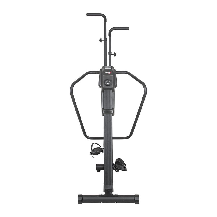
Page 4: Product Description
PRODUCT DESCRIPTION Height adjusting knob Console Resistance knob Handle Pedal Transport wheel Level feet... -
Page 5: Assembly
ASSEMBLY Unpack all parts to clean area. Check that all parts are present. Do not dispose the packing material before the assembly is completed. Tools and hardware are included. Handlebar (25, 26) Upper handlebars (39, 40) Rear handlebars (41, 42) Leveling feet (62) Adjusting knobs (28) Pedals (35, 36) -
Page 6: Step 1
Hardware Spacer (8 x 12 x 5mm) 2 pcs Washer (8 x 25 x 3.0t) 4 pcs Nut (M8x p1.25) 6 pcs Allen bolt (M8 x p1.25 x 25 mm) 2 pcs Carriage bolt (M8 x p1.25 x 85 mm) 4 pcs Multi wrench tool with screwdriver Allen key... -
Page 7: Step 2
After placing in the required place, check the stability of the machine. If the machine is not level, proceed as follows: Loosen the foot (62), the plate will release. Adjust the height of the leveling foot (62) with one hand. Once the machine is level, secure the foot with the other hand using the plate (103) to a stable position. -
Page 8: Step 3
STEP 3 Attach the main frame (53) to the base (60) and connect with 6x bolts (98). Note: Do not tighten the screws yet. -
Page 9: Step 4
STEP 4 The bolts (97) are pre-mounted on the main frame (53). Unscrew the bolts for the next procedure. Attach the support tube (55) to the base (60) and main frame (53) with 2x bolts (97 and 98). Make sure that the bolts are tightened. -
Page 10: Step 5
STEP 5 The machine is designed so that there are 2 types of pedal heights (406 mm and 508 mm) according to the user's needs. The figure below shows the mounting options and type for each option. Attach the cable (18) to the pedal holder (38) and tighten with 1x bolt (81), 2x washers (66), 1x spacer (32) and nuts (71). -
Page 11: Step 7
STEP 7 Bolts (98) are screwed in front of the handles (42). You must unscrew the bolts for the next steps. Connect the right handles (40 and 42) with 1x bolts (98). Do not tighten the screws. Repeat for the left side. Remove the 2x bolts (98) from the support rod (55) for the next step. -
Page 12: Step 8
Attach the handles (40) to the handle holders (46, 56) with 2x bolts (98). Make sure that the handles are properly fastened. Repeat on the other side. STEP 8 Attach the right handle (26) to the bracket (30). Select the appropriate height (5 positions to choose from) and tighten the hand screw. -
Page 13: Step 9
STEP 9 Release the clip on the console (38) and disconnect the cables. The console (38) is powered by two AAA batteries. Attach the console (38) back to the frame. Note: • Do not damage the cables. • Do not mix new and old batteries. •... -
Page 14: Moving
MOVING • You must screw up the leveling feet to move. • Hold the rear stabilizer (58) with two hands and move it with the transport wheels. • The floor must be leveled. -
Page 15: Placement
PLACEMENT Place the machine on an area of at least 1300 x 1000 x 2500 mm (l x w x h). Make sure that there is enough space around the machine for free movement. -
Page 16: Console
CONSOLE Turning on Any movement or pressing of the button turns on the console. Make sure the batteries are inserted. Turning off The console automatically shuts off after 4 minutes of inactivity. All values are reset. -
Page 17: Buttons
BUTTONS Press the MODE button to change the displayed data: SPEED, DISTANCE, TIMER, COUNT, CALORIES. Holding down the MODE button resets the values. FUNCTION SCAN Automatically displays SPEED, DISTANCE, TIMER, COUNT and CALORIES data, the displayed data changes every 5 seconds. To start the function, select the SCAN with MODE button. -
Page 18: Use
SPEED TRACKER The console display two speed indicators on the sides of the display. The indicators copy your speed. The device is designed to copy the same movement as when climbing. You will exercise the upper and lower parts of your body, improve your metabolism, and burn more calories. Your body weight provides enough resistance for exercise. -
Page 19: Exercise Instructions
Regularly measure your heart rate. If your device is not equipped with a heart rate monitor, talk to your doctor about how you can measure the heart rate yourself. Determine the interval in which your heart rate will move, so training will be more effective. Consider your age and physical condition. The following table is used to determine the optimal heart rate interval: Heart rate frequency 50-75% (from maximum heart rate) –... -
Page 20: The Cool Down Phase
Hamstring stretched Sit and outstretch your right leg. Rest the sole of your left foot against the inside of your right tight. Stretch out your right arm along your right leg as far as you can. Hold for 15 seconds and relax. Repeat all with your left leg and left arm. -
Page 21: Diagram
DIAGRAM... -
Page 23: Parts List
PARTS LIST Name Qty. Name Qty. Spacer (10x14x15 mm) Right pedal Bearing (6800) Left pedal bracket Pulley Right pedal bracket Flywheel Left upper support handle Tension bracket Right upper support handle Eye Bolt (67 mm) Left bottom support handle Resistance bracket Right bottom support handle Bearing adapter Handlebar bush... -
Page 24: Environment Protection
Hardware Nylon nut (M8×p1.25) Bolt (M8×p1.25×85 mm) Nylon nut (M10×p1.5) Bolt (M10×p1.5×30 mm) Thin nylon nut (M10×p1.5) Bolt (M10×p1.5×100 mm) Bolt (M10×p1.5×110 mm) Screw (M4×32 mm) Screw (M5×18 mm) Bolt (M8×p1.25×20 mm) Screw (M5×p0.8×20 mm) Bolt (M5×p0.8×10 mm) Bolt (M5×p0.8×15 mm) Bolt (L=30mm) Bolt (M6×p1.0×12 mm) Bolt (M8×p1.25×85 mm) - Page 25 otherwise specified in the Purchase Agreement, in the Amendment to this Contract or in another written agreement. Warranty Conditions Warranty Period The Seller provides the Buyer a 24 months Warranty for Goods Quality, unless otherwise specified in the Certificate of Warranty, Invoice, Bill of Delivery or other documents related to the Goods. The legal warranty period provided to the Consumer is not affected.
- Page 26 26847264 VAT ID: CZ26847264 Phone: +420 556 300 970 E-mail: eshop@insportline.cz reklamace@insportline.cz servis@insportline.cz Web: www.inSPORTline.cz inSPORTline s.r.o. Headquaters, warranty & service center: Električná 6471, Trenčín 911 01, SK CRN: 36311723 VAT ID: SK2020177082 Phone: +421(0)326 526 701 E-mail: objednavky@insportline.sk reklamacie@insportline.sk servis@insportline.sk...
Need help?
Do you have a question about the Verticon 21964 and is the answer not in the manual?
Questions and answers