Table of Contents
Advertisement
Advertisement
Table of Contents

Related Manuals for Vinten Vision 30


Summary of Contents for Vinten Vision 30
- Page 1 Contents Next Previous Page View Vision 30 Vinten Camera Control Solutions...
-
Page 2: Pan And Tilt Head
Vinten Broadcast Limited. Vinten, Vision and Quickfit are registered trademarks of Vinten Broadcast Limited. - Page 3 Particular attention must be paid to cleaning, especially after use in adverse conditions. To order spare parts or to obtain further information, application should be made to Vinten Broadcast Limited or to your local distributor.
-
Page 4: Notes To Readers
Page Page View Notes to readers This is the on-line version of ‘Vision 30 Pan and Tilt Head Maintenance Manual’ (3259-9). Readers should be aware that the pagination differs between on-line and printed versions. Navigation Clicking the mouse on any blue text will move you around the document. - Page 5 First Previous Next Previous Page Page Page View Contents Page Foreword ................3 Notes to readers .
- Page 6 Page Fig 1.1 Vision 30 Pan and Tilt Head ............13 Fig 2.1 Balance Graph...
- Page 7 First Previous Next Previous Page Page Page View Contents (Cont) Page Fig 6.11 Pan Bar Assembly............. . . 76 Fig 6.12 Spherical Base .
-
Page 8: Safety - Read This First
Contents First Previous Next Previous Page Page Page View Safety - Read This First! Warning symbols in this maintenance manual Where there is a risk of personal injury, injury to others, or damage to the pan and tilt head or associated equipment, comments appear, highlighted by the word WARNING! and supported by the warning triangle symbol. - Page 9 Contents First Previous Next Previous Page Page Page View Abbreviations The following abbreviations are used in this publication: alternating current pound (weight) Amps Lubricated Friction across flats left hand as required MISO metric thread ASME American Society of Mech Engineers metre assy assembly...
-
Page 10: Technical Specification
Contents First Previous Next Previous Page Page Page View Technical Specification Weight 10 kg (22 lb) Height 230 mm (9 in.) Length 175 mm (7 in.) Width 245 mm (9.7 in.) Load capacity See balance graph Tilt range ±90° Pan range 360°... -
Page 11: Design Improvements
Contents First Previous Next Previous Page Page Page View Design Improvements SERIAL No. DETAILS INFORMATION... -
Page 12: Introduction And Description
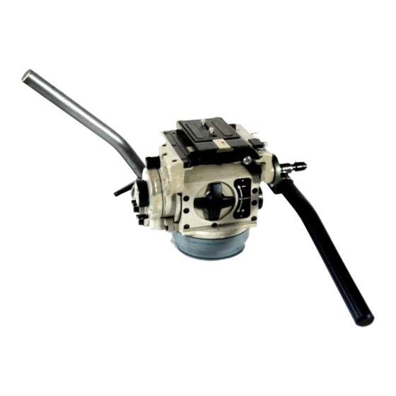
The Vision 30 head incorporates an improved version of the Vinten lubricated friction (L.F) system. The LF system allows the amount of drag for both the tilt and pan movements to be varied over a wide range to suit the operators preference and permits “whip-pan”... - Page 13 Page View Fig 1.1 Vision 30 Pan and Tilt Head The fixed base houses a bearing, part of the L.F. drag system and brake mechanism for the pan function. Two types of fixed base are available, namely flat (Types 3259-3D or 3F) or spherical (Types 3259-3E or 3S).
- Page 14 The camera may be attached directly to the platform slide plate via two screws passed through slots in the plate and screwed into the camera base. Alternatively the camera may be attached via a Vinten wedge assembly (Type 3761-13) and automatic wedge adaptor (Type 3761-3).
-
Page 15: Operation
................18 General The Vision 30 Head is part of a range including the Vision 5, 10 and 20 heads. It may be supplied already fitted in a carrying case within a packing case. -
Page 16: Installation
The four 3/8 in. BSW hex. headed bolts supplied, passed upwards through the support and screwed into the head base. or A Vinten Quickfix adaptor, in which case the four 3/8 in. BSW bolts are removed and the head is secured to the adaptor by tightening the three knurled headed screws of the adaptor. - Page 17 Contents First Previous Next Previous Page Page Page View engaged and then, mount and secure the camera/lens combination, with their combined centre of gravity approximately over the head tilt axis. Wedge adaptor fixing The adaptor (if not already fitted) is attached to the platform slide plate by either two 3/8 in. BSW screws passed through the slide plate slots into threaded inserts in the adaptor body, or by a minimum of four M4 screws passed through the adaptor body into the appropriate threaded holes in the slide plate.
-
Page 18: Balancing The Camera
View Balancing the camera Balancing the Vision 30 head achieves two objectives. Firstly, when a head is correctly balanced the operator will need a minimum amount of even effort to move the head. Secondly, once balanced, the head and its payload can be set to any tilt position and the head will maintain this position with “hands off”. - Page 19 Contents First Previous Next Previous Page Page Page View Setting the pan and tilt brakes Both the PAN BRAKE and TILT BRAKE are fully applied when the respective lever on the left hand side of the head is rotated fully clockwise. Operation WARNING!: The tilt centre lock must be engaged and the pan and tilt brakes must be applied before any attempt is made to fit or remove any equipment mounted on the pan...
-
Page 20: Tools And Materials
No special tools are required Consumable materials The following consumable materials are required for certain procedures in Section 5. NOTE: :Adhesives and lubricants are not supplied by Vinten Broadcast Ltd and should be obtained under local arrangements. ITEM PART No. -
Page 21: Brake Adjustment
..............6 General The Vision 30 pan and tilt head is robustly made to high engineering standards and little attention is required to maintain serviceability save regular cleaning. Attention to the following points will ensure a long and useful life with minimum need for repair. - Page 22 Contents First Previous Next Previous Page Page Page View The procedure for resetting the pan and tilt brake knobs is as follows: Apply the brakes. Referring to 6.2, remove the grubscrew (54) and pull the knob (53) off the shaft. Ensure knob retainer (53A) remains on shaft.
- Page 23 Contents First Previous Next Previous Page Page Page View Section 5 Repair Contents Para Repair ................25 Section 5 - Repair Repair .
- Page 24 Contents First Previous Next Previous Page Page Page View Mechanism block and secondary spring assemblies ........31 Mechanism block and secondary spring assemblies .
- Page 25 Broadcast Ltd or your local distributor. The Vision 30 pan and tilt head may be divided into a number of separate assemblies to facilitate repair. In use the head will have various accessories, zoom and focus controls viewfinders etc., which must be removed before dismantling the basic head.
-
Page 26: Platform Assembly
Contents First Previous Next Previous Page Page Page View The primary mechanism assembly. The primary mechanism assembly consists of the following main components/assemblies. The main casting with associated parts. The loading bars which operate in conjunction with the mechanism block assembly. The tilt drag lubricated friction mechanism. -
Page 27: Top Cover
Contents First Previous Next Previous Page Page Page View 10.3 The adaptor assembly is refitted by a reversal of this procedure. Dismantle To dismantle the platform assembly (Fig 6.8),proceed as follows 11.1 Unscrew and remove two M3 pan head screws (129) and slide out gib strip (218). 11.2 Tap out spirol pin (212) from one slide adjuster knob (211) and remove knob with its shim (159). -
Page 28: Front Cover
Contents First Previous Next Previous Page Page Page View Refit The top cover is refitted by a reversal of the procedure detailed at Para 14, ensuring the left-hand end is flush with the main casting (61) (Fig 6.3). Front cover Remove The front cover (32) is removed as follows (Fig... - Page 29 Contents First Previous Next Previous Page Page Page View Refit The end plate/adjustment thread assembly is refitted as follows (Fig 6.7 6.2): 19.1 Insert main spring (28) into mechanism block (12). 19.2 Grease thread of main spring adjustment shaft (191) with molybdenum disulphide grease GP50. 19.3 Ensure adjustment nut (201) assembled to collar (197) is screwed up to thrust race (192) on end bracket (195) by turning adjustment knob (186) fully counter-clockwise.
- Page 30 Contents First Previous Next Previous Page Page Page View 21.1.1 Slacken M3 socket head grubscrew (20) securing axle-cross member roller (19). 21.1.2 Press out axle (19) and remove track roller (17) and its associated shims (18). 21.2 For each lateral guide roller (22) on rear cross member (21): 21.2.1 Unscrew and remove M4 button head screw (24).
- Page 31 Contents First Previous Next Previous Page Page Page View Mechanism block and secondary spring assemblies Remove The mechanism block assembly (12) is removed as follows (Fig 6.6): 24.1 Remove platform assembly as detailed at Para 24.2 Remove top cover as detailed at Para 24.3 Remove front cover as detailed atPara...
- Page 32 Contents First Previous Next Previous Page Page Page View Buffer pad renewal In the event that any of the buffer pads on the mechanism block assembly or the secondary spring assembly have deteriorated they should be replaced. Remove all traces of the defective pad and adhesive, ensure both pad and component are free from greasy deposits (use IS Quick Clean) and secure new pads with Loctite adhesive IS495.
-
Page 33: Base Assembly
Contents First Previous Next Previous Page Page Page View 30.2.2 Adjust adjustable axle (87) (Fig 6.3) until block ceases to rock. 30.2.3 Tighten locking screw (5) and recheck block for stability. 30.2.4 Repeat Para 30.2.1 Para 30.2.3 if necessary. 30.3 Refit two plunger (carriage assemblies) (25), springs (26) and spring plugs (27) removed at Para 24.7. - Page 34 Contents First Previous Next Previous Page Page Page View Pan drag unit assembly Remove The pan drag unit assembly (3) is removed as follows (Fig 6.2): 35.1 Align two notches in periphery of pan drag unit assembly (3) with securing screws (10) of brake flange assembly (9).
- Page 35 Contents First Previous Next Previous Page Page Page View 37.6 Separate friction shoe carrier-top (228) from pan drag housing (226). 37.7 Inspect ’O’ rings (232) and (148) and omniseal (153) for deterioration or damage. To dismantle the pan unit bearing sub-assembly proceed as follows (Fig 6.9): 38.1 Unscrew and remove two M3 Posidriv countersunk head screws (106) locking bearing nut (225)
- Page 36 40.10 Swing a friction shoe assembly (144) outwards, fit an actuator rod (with each end lubricated with Vinten Fluid No. 3 into its location in drag actuator shaft (230) and swing friction shoe assembly (144) inwards locating outer end of drag actuator rod (151) in the cup in friction shoe assembly (144).
- Page 37 Contents First Previous Next Previous Page Page Page View 43.3 Ensure square end of drag actuator shaft (230) engages correctly with aperture of pan drag lever (76) within primary mechanism assembly (2). If difficulty is experienced reposition drag lever by adjustment of pan drag knob (49).
- Page 38 Contents First Previous Next Previous Page Page Page View Dismantle To dismantle a loading bar assembly continue as follows (Fig 6.3): 45.1 For each yoke type track roller-follower (125): 45.1.1 Press out spirol pin (127) from interference fit side of loading bar (one side is clearance).
- Page 39 Contents First Previous Next Previous Page Page Page View Refit The LH or RH loading bar assembly is refitted as follows (Fig 6.3): 47.1 Apply white bearing grease to both washers-actuator bearing (120) and drawn cup needle bearing (123). 47.2 Fit washer-actuator bearing (120) to side plate assembly (82) or tilt drag unit assembly (100) stub shaft (134) with the chamfer of washer (120) towards stub shaft (134) shoulder.
- Page 40 Contents First Previous Next Previous Page Page Page View 50.2 Re-attach PAN DRAG label (52) with Scotch Y909 adhesive tape. 50.3 Refit RH loading bar assembly (119) as detailed at Para 50.4 Comply with Para Tilt drag unit assembly To repair components of the tilt drag unit in isolation and in situ, it is only necessary to follow the procedure detailed in Para 52.3 Para 52.5...
- Page 41 55.1 Lightly apply white bearing grease to all moving contact surfaces particularly ’O’ rings (148), friction shoe assembly (144) pivot blades, friction shoe pivots (143), and omniseal (153). Lubricate each end of actuator rods (151) with Vinten Fluid No. 3. 55.2 Reassemble any parts of the tilt drag unit dismantled at Para 54.9.
- Page 42 Further assembly of the tilt drag unit should be performed over a shallow tray to catch any spilt fluid. Continue as follows: 56.1 Supporting the tilt drag unit with drag adjustment stud (150) upwards, introduce Vinten Fluid No. 3 into tilt drag housing (141) ensuring the fluid fills the space below friction shoe carrier-top (142). This is a slow process and sufficient time for fluid settlement must be allowed.
-
Page 43: Other Components
Contents First Previous Next Previous Page Page Page View Other components Bearings Regreasing of the four bearings (62, Fig 6.3 6.9) and the bearing (65, 6.3) can be accomplished with the bearings in situ after gaining access by removing the appropriate assemblies. Should a bearing require replacement the casting in which it is mounted must be heated to 120°C to free the bearing. - Page 44 Contents First Previous Next Previous Page Page Page View 63.3 For the adjustable roller: 63.3.1 Remove side plate assembly (82) as detailed at Para 63.3.2 Unscrew and remove M5 socket cap head screw (5) and washer (88). 63.3.3 Remove adjustable axle (87) and remove roller (17) and two shims (18) Refit A lower carriage roller (17) is refitted as follows (Fig...
- Page 45 Contents First Previous Next Previous Page Page Page View 66.2 Position right hand guide roller track block (92) 10.000 mm to 10.050 mm from left hand track block (89) and secure with two M4 screws (10) removed at Para 65.2. 66.3 Check gap measurement and parallelism of track blocks.
- Page 46 Contents First Previous Next Previous Page Page Page View 70.3 Remove mechanism block assembly as detailed at Para 70.4 Remove side cover as detailed at Para 52.3. 70.5 Remove bearing bracket as detailed at Para 52.4 Para 52.5. 70.6 Unscrew and remove two M4 button head screws (75) and remove brake housing top-pan (74). 70.7 Lift out two cylindrical rollers (73).
-
Page 47: Illustrated Parts List
............84 Introduction This parts list is issued for the Vision 30 pan and tilt heads manufactured by VINTEN BROADCAST LIMITED, Western Way, Bury St Edmunds, Suffolk, IP33 3TB, England. -
Page 48: Ordering Spare Parts
Vision 30 Pan & Tilt Head - with spherical base 3259-3E Vision 30 Pan & Tilt Head - with four-hole flat base and automatic wedge adaptor 3259-3F Vision 30 Pan & Tilt Head - with spherical base and automatic wedge adaptor... - Page 49 Contents First Previous Next Previous Page Page Page View V30_6_01 Fig 6.1 Vision 30 Pan and Tilt Head...
- Page 50 Contents First Previous Next Previous Page Page Page View Fig 6.1 Vision 30 Pan and Tilt Head Item Part No. Nomenclature 3259-3D Vision 30 pan and tilt head (flat base) 3259-11 Secondary mechanism assembly Fig 6.2 3219-42 Telescopic pan bar, consisting of:...
- Page 51 Contents First Previous Next Previous Page Page Page View Fig 6.1 Vision 30 Pan and Tilt Head (Cont) Item Part No. Nomenclature 3259-3S Vision 30 pan and tilt head (spherical base and automatic wedge adaptor) ABCF 3259-3E Vision 30 pan and tilt head (spherical base)
- Page 52 Contents First Previous Next Previous Page Page Page View 17,18 82 Ref Fig 6.4 100 Ref Fig 6.5 119 Ref Fig 6.3 V30_6_02 Fig 6.2 Secondary Mechanism Assembly...
- Page 53 Contents First Previous Next Previous Page Page Page View Fig 6.2 Secondary Mechanism Assembly Item Part No. Nomenclature 1 Ref 3259-11 Assembly, Secondary Mechanism, comprising: 3259-14 Assembly, primary mechanism Fig 6.3 3259-19 Assembly, pan drag unit, secured by: Fig 6.9 M006-704 Screw, skt cap hd M5 x 16 mm lg M006-703...
- Page 54 Contents First Previous Next Previous Page Page Page View Fig 6.2 Secondary Mechanism Assembly (Cont) Item Part No. Nomenclature J532-037 Spring, compression Flexo 102908 3259-231 Plug, spring J532-084 Spring, compression Terry Barnes 53700 3259-12 Assembly, end plate/adjustment thread, secured by: Fig 6.7 M007-524 Screw, skt butt hd M6 x 25 mm lg...
- Page 55 M004-804 Screw, skt grub M3 x 10 mm lg 3199-301 Label, tilt brake 3199-302 Label, pan brake 3259-333 Label, Vision 30, secured by: L102-001 Screw, hammerdrive, 00 x 1/8 in. 3259-289 Screw, slide clamp 3259-316 Label, warning, secured by: L102-001 Screw, hammerdrive, 00 x 1/8 in.
- Page 56 Contents First Previous Next Previous Page Page Page View V30_6_03 Fig 6.3 Primary Mechanism Assembly...
- Page 57 Contents First Previous Next Previous Page Page Page View Fig 6.3 Primary Mechanism Assembly Item Part No. Nomenclature 2 Ref 3259-14 Assembly, primary mechanism, comprising: 3259-206 Casting, main P200-229 Bearing, FAG 61809, secured by: M004-901 Screw, skt csk hd M3 x 8 mm lg 3259-271 Retainer, bearing 3259-272...
- Page 58 Contents First Previous Next Previous Page Page Page View Fig 6.3 Primary Mechanism Assembly (Cont) Item Part No. Nomenclature 3259-275 Retainer, drag knob, secured by: M003-102 Screw, csk hd, M2.5 x 6 mm lg P603-003 Roller, yoke type, track INA RST05TNX 3259-210 Shim, carriage roller 3259-209...
- Page 59 Contents First Previous Next Previous Page Page Page View Fig 6.3 Primary Mechanism Assembly (Cont) Item Part No. Nomenclature P605-001 Snap ring, FAG WR45 3259-24 Assembly, brake segment, comprising: 3259-302 Segment, brake 3259-301 Pad, brake 3259-23 Assembly, brake flange - tilt, secured by and comprising: M005-508 Screw, butt hd, M4 x 20 mm lg 3259-330...
- Page 60 Contents First Previous Next Previous Page Page Page View Fig 6.3 Primary Mechanism Assembly (Cont) Item Part No. Nomenclature 3259-217 Axle, roller vertical actuator M806-032 Pin, spirol 1.5 mm dia x 16 mm lg 3259-219 Strip, pressure, secured by: L800-007 Pin, spirol, headed, 5/64 in.
- Page 61 Contents First Previous Next Previous Page Page Page View 133A V30_6_04 Fig 6.4 Side Plate Assembly...
- Page 62 Contents First Previous Next Previous Page Page Page View Fig 6.4 Side Plate Assembly Item Part No. Nomenclature 82 Ref 3259-17 Assembly, side plate, comprising and secured by: 133A 3259-901SP Plate, side LH, comprising: 3259-281 Plate, side LH M850-007 Insert, Helicoil M8 x 1D lg 3259-270 Shaft, stub M006-905...
- Page 63 Contents First Previous Next Previous Page Page Page View 141A V30_6_05 Fig 6.5 Tilt Drag Unit Assembly...
- Page 64 Contents First Previous Next Previous Page Page Page View Fig 6.5 Tilt Drag Unit Assembly Item Part No. Nomenclature 100 Ref 3259-18 Assembly, tilt drag unit, comprising and secured by: 141A 3259-902SP Tilt drag housing assy (helicoil) comprising: 3259-264 Housing, tilt drag M850-007 Insert, Helicoil M8 x 1D lg 3259-270...
- Page 65 Contents First Previous Next Previous Page Page Page View Fig 6.5 Tilt Drag Unit Assembly (Cont) Item Part No. Nomenclature 3259-280 Knob, secured by: M600-006 Washer, plain M5 M500-080 Nut, M5 3259-338 Label, centre lock 3259-334 Plate, serrated, secured by: M006-903 Screw, skt.
- Page 66 Contents First Previous Next Previous Page Page Page View V30_6_06 Fig 6.6 Mechanism Block and Secondary Spring Assemblies...
- Page 67 Contents First Previous Next Previous Page Page Page View Fig 6.6 Mechanism Block and Secondary Spring Assemblies Item Part No. Nomenclature 3259-15 Assembly, mechanism block, comprising: 3259-208 Block, balance mechanism 3259-233 Track, vertical face, secured by: L800-007 Pin, spirol, headed, 5/64 in. dia. x 1/4 in. lg 3259-234 Track, horizontal face, secured by: L800-007...
- Page 68 Contents First Previous Next Previous Page Page Page View V30_6_07 Fig 6.7 End Plate/Adjustment Thread Assembly...
- Page 69 Contents First Previous Next Previous Page Page Page View Fig 6.7 End Plate/Adjustment Thread Assembly Item Part No. Nomenclature 29 Ref 3259-12 Assembly, end plate/adjustment thread, comprising: 3259-241 Knob, adjustment Q001-018 ‘O' ring. R2043 GACO M701-030 Washer, starlock BV6704 Baker and Finnemore 3259-240 Knob, adjustment centre, secured by: M004-901...
- Page 70 Contents First Previous Next Previous Page Page Page View V30_6_08 Fig 6.8 Platform Assembly...
- Page 71 Contents First Previous Next Previous Page Page Page View Fig 6.8 Platform Assembly Item Part No. Nomenclature 38 Ref 3259-13 Assembly, platform, comprising: 3259-282 Platform 3259-292 Block, threaded, secured by: M005-902 Screw, skt. csk. hd. M4 x 10 mm lg 3259-291 Stud, slide adjuster 3259-293...
- Page 72 Contents First Previous Next Previous Page Page Page View V30_6_09 Fig 6.9 Pan Drag Unit Assembly...
- Page 73 Contents First Previous Next Previous Page Page Page View Fig 6.9 Pan Drag Unit Assembly Item Part No. Nomenclature 3 Ref 3259-19 Assembly, pan drag unit, comprising: 3259-204 Housing, bearing P200-229 Bearing, FAG 61809 N552-014 Bearing, needle thrust, NTA4458 Torrington N552-015 Washer, needle thrust, TRA 4458 Torrington 3259-205...
- Page 74 Contents First Previous Next Previous Page Page Page View V30_6_10 Fig 6.10 Quadrant Assembly...
- Page 75 Contents First Previous Next Previous Page Page Page View Fig 6.10 Quadrant Assembly Item Part No. Nomenclature 241 Ref 3259-30 Assembly, quadrant, comprising: 3259-321 Stud, quadrant 3259-332 Nut, quadrant wing, secured by: M806-036 Pin, spirol, 2 mm dia x 14 mm lg 3089-335 Clamp, pan bar M600-009...
- Page 76 Contents First Previous Next Previous Page Page Page View V30_6_11 Fig 6.11 Pan Bar Assembly...
- Page 77 Contents First Previous Next Previous Page Page Page View Fig 6.11 Pan Bar Assembly Item Part No. Nomenclature 248 Ref 3219-43 Assembly, telescopic pan bar, comprising: 3219-44 Pan bar, fixed, consisting of: 3219-600 Spigot 3219-255 Tube 3219-227 Sleeve J550-074 Hole plug 3219-38 Pan bar, sliding, consisting of: 3219-253...
- Page 78 Contents First Previous Next Previous Page Page Page View Fig 6.1 Item V30_6_22 Fig 6.12 Spherical Base...
- Page 79 Contents First Previous Next Previous Page Page Page View Fig 6.12 Spherical Base Item Part No. Nomenclature 266 Ref 3259-25 Assembly, spherical base, comprising: 3259-201 Base, spherical 3259-327 Stud, clamp 3390-18 Bowl clamp knob assembly, comprising: 3390-228 Bowl clamp knob, secured by: M701-031 Circlip, external 1400-14 3390-228...
- Page 80 Contents First Previous Next Previous Page Page Page View Fig 6.1 Item V30_6_13 Fig 6.13 Flat Base Assembly...
- Page 81 Contents First Previous Next Previous Page Page Page View Fig 6.13 Flat Base Assembly Item Part No. Nomenclature 276 Ref 3259-25 Assembly, flat base, comprising: 3259-202 Base, Flat L850-052 Insert, Helicoil 3/8 in. BSW x 1D...
- Page 82 Contents First Previous Next Previous Page Page Page View 282A V30_6_14 Fig 6.14 Automatic Wedge Adaptor and Wedge Assemblies...
- Page 83 Contents First Previous Next Previous Page Page Page View Fig 6.14 Automatic Wedge Adaptor and Wedge Assemblies Item Part No. Nomenclature 281 Ref 3761-3 Assembly, automatic wedge adaptor, comprising: 282A 3761-900SP Wedge adaptor (spares), comprising: 3761-201 Body L850-052 Helicoil 3/8 BSW x 1D M806-027 Pin, spirol, 3 mm dia x 14 mm lg 3761-202...
- Page 84 Contents First Previous Previous Page Page View Fig 6.15 Composite Spare Parts Part No. Nomenclature 3259-900SP Bearing bracket assembly (Heli-coil), consisting off: 3259-207 Bearing bracket M850-006 Insert, Heli-coil, M8 x 1.5 D lg 3259-901SP Side plate assembly (Heli-coil), consisting off: 3259-281 Side plate M850-007...
Need help?
Do you have a question about the Vision 30 and is the answer not in the manual?
Questions and answers