Table of Contents
Advertisement
Quick Links
NAV SD 511 • Setup Guide
CLASS 1 LASER PRODUCT, see
WARNING:
The NAV SD 511 output continuous invisible light (Class 1 rated), which may be harmful to the eyes; use with caution.
•
Do not look into the fiber optic cable connectors or into the fiber optic cables themselves.
•
Plug the attached dust caps into the optical transceivers when the fiber cable is unplugged.
AVERTISSEMENT :
pour les yeux ; à utiliser avec précaution.
•
Ne pas fixer directement les connecteurs optiques ou les câbles fibre optique.
•
Associez les bouchons anti-poussière à l'ensemble émetteur/récepteur optique lorsque le câble fibre optique est débranché.
This guide provides instructions for an experienced installer to install the Extron NAV SD 511 scaling decoders and to make all
connections. One or more compatible Extron NAV encoders and one or more decoders form an AV distribution and switching matrix on a
managed 1G IP network.
NOTE
For more information on any subject in this guide, see the NAV SD 511 User Guide, available at
:
Installation
Step 1 — Mounting
Turn off or disconnect all equipment power sources and mount the decoder as required.
Step 2 — Rear Panel Connections
POWER
12V
2.0 A MAX
H
H H
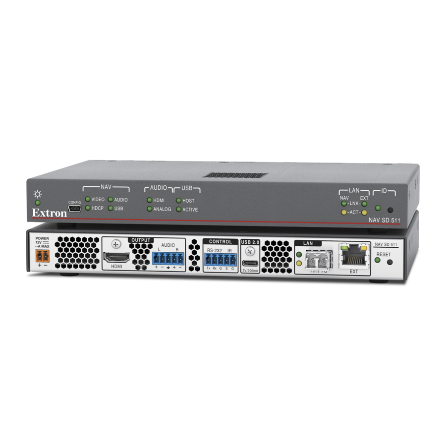
NAV SD 511 Rear Panel Features
Figure 1.
A
NAV 1G port — Use a pair of fiber cables to connect to a LAN on which one or more encoders also reside for streaming and control.
Ensure that you use the proper fiber cable for your decoder. Typically, singlemode fiber has a yellow jacket
NOTE:
and multimode cable has an orange or aqua jacket.
B
Extension port — If desired, connect another networked device to this port. The port acts as a networked 1G switch to the NAV 1G
port.
C
HDMI output port — Connect an HDMI cable between this port and an HDMI display (or a DVI display, with an appropriate adapter).
See
LockIt
Lacing Brackets
®
D
Audio output port — This 5-pole, 3.5 mm captive screw connector outputs the streamed, unamplified, line level analog audio. Connect
an audio device, such as an audio amplifier or powered speakers (see
connector).
E
Control RS-232/IR port — Connect a serial RS-232 signal, a modulated IR signal, or both to this 3.5 mm, 5-pole captive screw
connector for bidirectional RS-232 and IR communication with connected remote controlled devices using an Extron control system
(see
Control connector
F
USB 2.0 port — Connect a USB Type-C cable to USB host or a USB device. See
fasten the USB connector to the decoder.
This connector is limited to supplying 200 mA in USB device mode.
NOTE:
NAV SD 511
Le NAV SD 511 émettent une lumière invisible en continu (équipement de classe 1) qui peut être dangereuse
OUTPUT
AUDIO
L
R
HDMI
C
C C
D
D D
on page 6 to use the LockIt HDMI Cable Lacing Bracket to secure the connector to the decoder.
on page 6 to wire the connector).
User Guide at
www.extron.com
CONTROL
USB 2.0
RS-232
IR
Tx Rx G S G
5V/200 mA
E
E E
F
F F
Analog audio output connector
www.extron.com
LAN
NAV 1G
EXT
A
A A
B
B B
on page 6 to wire the
LockIt
Lacing Brackets
on page 6 to securely
®
.
NAV SD 511
RESET
G
G G
1
Advertisement
Table of Contents

Related Manuals for Extron electronics NAV SD 511


Summary of Contents for Extron electronics NAV SD 511
- Page 1 WARNING: The NAV SD 511 output continuous invisible light (Class 1 rated), which may be harmful to the eyes; use with caution. • Do not look into the fiber optic cable connectors or into the fiber optic cables themselves.
- Page 2 Reset button (see figure 1 on page 1)— This button initiates three modes of reset (see the NAV SD 511 User Guide, available at www.extron.com, for details). Power connector Power connector — Plug the included external 12 VDC power supply into this 2-pole connector (see on page 6 to...
- Page 3 NOT operational until the boot process is complete (the Power LED is lit steadily) System Operation The decoder can be configured and controlled using embedded web pages or Extron Toolbelt (see the NAV SD 511 User Guide available www.extron.com and the Toolbelt Help file).
- Page 4 Press the keyboard <Enter> key. The browser displays a privacy error message (see figure 3 at right for an example in the Chrome browser). Click Advanced (see figure 3, ). The button changes to Hide Advanced and explanatory text and a link appear below the button.
- Page 5 NAV SD 511 • Setup Guide (Continued) NOTE: Detailed descriptions of communication, configuration, and monitoring are provided in the NAV SD 511 User Guide, available at www.extron.com. Connection settings View and change connection settings as follows: On the home page, click Settings (see figure 5, ) and then Network Connection ( ).
- Page 6 Connection Details LockIt Lacing Brackets ® Plug the HDMI or USB cable into the panel connection (see , at right for an HDMI example). Loosen the connection mounting screw from the panel enough to allow the LockIt lacing bracket to 3 3 3 be placed over it ( ).
Need help?
Do you have a question about the NAV SD 511 and is the answer not in the manual?
Questions and answers