
Subscribe to Our Youtube Channel
Related Manuals for Polivac Terminator


Summary of Contents for Polivac Terminator
- Page 1 Polivac Terminator Carpet Extractor Machine Operations Manual & Trouble Shooting Guide...
-
Page 2: Technical Specification
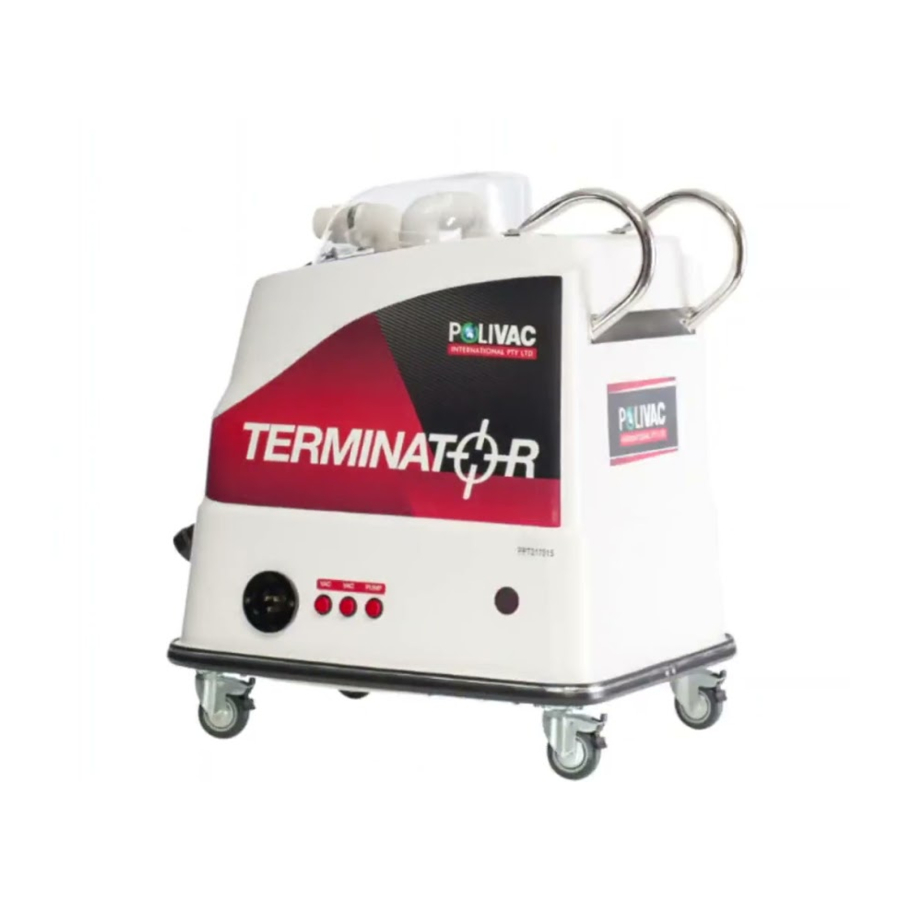
Polivac Terminator Carpet Extractor Machine Technical Specification Vacuum system 2 x 1100 watt 2 stage tangential motors Solution Pump 1 x 220 psi sealed electric pump 240v 10A Fibreglass body with Aluminum sub frame Switches 3 x Red self-illuminating push button switches. - Page 3 1. 240v power socket inlet. 2. Vacuum # 1 on/off switch 3. Vacuum # 2 on/off switch 4. Solution Pump on/off switch.
- Page 4 1. Solution outlet fitting. 2. Waste water dump valve Pictured above shows the waste water dump valve in the up position allowing the water to be Emptied & disposed of. The valve is a slide gate sealed unit that only requires operator To lift up to dispense water &...
- Page 5 Pictured above is the water cut off system used in the Terminator. The Float switch cut off waste water from entering the vac motors. This is the working position of the float. 1)Please note once dirt water level reach the float switch trigger, whole machine will stop working.
- Page 6 The above picture shows the exhaust point for the vacuum motors. If at any stage the operator experiences water coming from this point it indicates Foam is passing by the filter & this needs to be stopped. Water coming from this point Can only come thru the vac motors.
- Page 7 Fig 7 1 x 5mtr solution hose Fig 8 1 x 12" Floor Wand Fig 9...
- Page 8 Operational instructions for Terminator 1. Connect power cable to 240v socket inlet (Fig 1 # 1) 2. Connect the male end of solution hose (Fig 8) to the solution outlet on machine (Fig2) 3. Connect the female solution hose end to the male connection of the wand trigger (Fig 9) 4.
-
Page 9: Cabinet Assembly
Terminator Cabinet Assembly Drawings by: LeanSynergicDesign.com.au... - Page 10 PPR013 Filter Screen PM037A Cap for the Filter PPR135 Button & Loop Set PPR098 4 X 16 mm Pak Phillip PM028A Pullman / Terminator handle PM055 Plastic Elbow PPR144 Float Switch PPT022 Float Switch Bracket PM033 90 Deg Elbow PPR114...
-
Page 11: Frame Assembly
Terminator Frame Assembly Drawings by: LeanSynergicDesign.com.au... -
Page 12: Frame Assembly Parts List
Terminator Frame Assembly Parts List No Code Description PPR005 Side Frame 25x25x3x390 mm PPR006 Front Frame 25x25x3x320 mm PPR007 Rear Frame 25x25x3x360 mm PPR009 Wheel Plate PPT003 Castor Wheel PPT002 Bottom Cover PPR090 6 X 20 mm SS AAA354 6 mm Nyloc Nut... -
Page 13: Under Carriage Assembly
Terminator Under Carriage Assembly Drawings by: LeanSynergicDesign.com.au... - Page 14 Terminator Under Carriage Assembly Parts List No Code Description PPR022 Round Switch PPR048 Inlet Socket PPR098 Pan Phillips PVT025 Stainless Washer PPR095 Nyloc Nut PPR059A Reducer PPR032 Monel Screen PM064 Female to Male Adaptor PM032 90 Deg Female with Flange...
- Page 15 Use of non-approved chemicals and detergents in the product will void the warranty. 10. Products that have been modified are not covered by warranty. 11. Products that have not been serviced at their recommended intervals by an authorised Polivac Service Centre or Agent are not covered by warranty 12.
Need help?
Do you have a question about the Terminator and is the answer not in the manual?
Questions and answers