Table of Contents
Advertisement
Quick Links
Advertisement
Table of Contents

Related Manuals for Pyle Pro PDWM4350U


Summary of Contents for Pyle Pro PDWM4350U
- Page 1 PDWM4350U PDWM4360U PDWM4350U - PDWM4360U UHF Wireless Microphone System Kit...
-
Page 2: System Features
CATALOG Please read the instructions carefully to ensure proper use and operation of the product. Also, keep the instructions for future reference. 1. FOREWORD This professional wireless microphone system operates on high-e ciency, - - - - - - - - - - - - - - - - - - - - - - - - - - - - - - - - - - - - - - - - - - - - - - - - - - - - - - - - - - - - - - - - - - - - - - - - - - - - - - - - - - - - - - - - - - - - - low-consumption discharging techniques. -
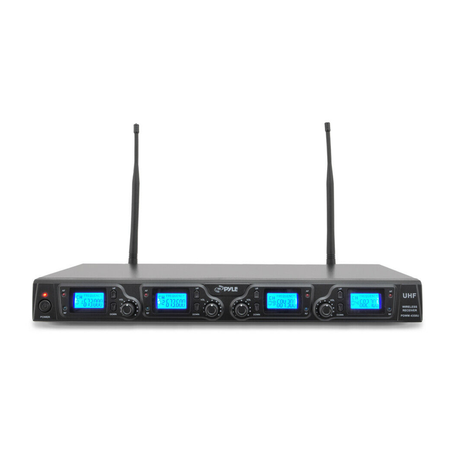
Page 3: Four Channel Receiver Features
FOUR CHANNEL RECEIVER FEATURES MICROPHONE-TRANSMITTER FEATURES 1. Power Button: Power ON/OFF the receiver. 2. Power Indicator: Indicate the power ON/OFF. 1. Grille: Protects the cartridge and help reducing the breath sounds and wind 3. LCD Information Display: Show the receiver frequency channel ect. noise. -
Page 4: Transmitter Battery Installation
BODY-PACK TRANSMITTER FEATURES TRANSMITTER BATTERY INSTALLATION 1. Battery Installation of Handheld Microphone: Open the battery cover. Insert the supplied batteries into battery jar in polarity and cover the battery. 2. Battery Installation of Bodypack Transmitter: Push open the battery cover. Insert the supplied batteries into battery jar in polarity and close the battery cover. -
Page 5: Bodypack Transmitter Connection
BODYPACK TRANSMITTER CONNECTION SYSTEM CONNECTION 1. Receiver Power Connection: Connect the DC connector of supplied AC/DC adapter Into the DC power input of receiver. Plug the AC Input connecter 1. Lavalier Microphone Connection: Connect the connector of supplied into an AC120/60Hz or AC220V/50Hz outlet. (Shown as below) lavalier microphone to the connecting jack of transmitter (shown as below) Set the transmitter work state in wireless lavalier system (L). -
Page 6: Troubleshooting
TROUBLESHOOTING SYSTEM SPECIFICATIONS • RF Carrier Frequency Range: PROBLEM INDICATOR STATUS SOLUTION Red transmitter Slide transmitter POWER ON/OFF switch Approximately 523 to 597.8 MHZ (Available frequencies depend on No Sound indicator is not to ON position. Make sure battery is inserted properly, observing battery (+/-). - Page 7 MORE THAN 10dBm Max Deviation ±70KHz Spurious Emission MORE THAN 55dB Dimensions 238MM X 50MM X 50MM BODY-PACK TRANSMITTER SPECIFICATIONS PDWM4350U Power Requirements 1.5VAA battery X2 Nominal Current Drain LESS THAN 100mA Modulation Type RF Output MORE THAN 10dBm Max Deviation ±70KHz...
Need help?
Do you have a question about the PDWM4350U and is the answer not in the manual?
Questions and answers