
Related Manuals for Erreka GLOBAL 4


Summary of Contents for Erreka GLOBAL 4
- Page 1 GLOBAL 4 SYSTEM TELESCOPIC 4 SYSTEM ACTUATOR FOR SLIDING DOORS INSTALLATION MANUAL...
-
Page 2: Table Of Contents
INTRODUCTION ERREKA Automatic Doors thanks you for the trust placed in us and for having selected a product that we manufacture. We recommend detailed reading of this installation manual for proper assembly, the performance of your automatic door will depend on the quality of your work. -
Page 3: Warning For Installer
- Before installing, please read this manual and follow all instructions. Otherwise, the installation may be faulty and may cause accidents and breakdowns. - ERREKA Automatic Doors will not be held liable for any damages caused by an installation not in accordance with this Installation Manual. -
Page 4: Electric Pre-Installation
4. ELECTRIC PRE-INSTALLATION Nº DESCRIPTION CABLES Power supply 3 wire hose (2,5mm 4 shielded wires Selector ( Bus CAN) (0,5mm Externak key KC y KB 3 wires (0,5mm Activation sensors+ photocell 8+8 wires (0,5mm Safety sensors 6+6 wires(0,5mm 5. TECHNICAL FEATURES CHARACTERISTICS G4 - Operator 870 T4- Operator 870... -
Page 5: Global Assembly
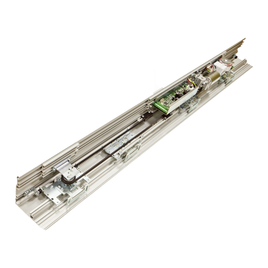
6. GLOBAL ASSEMBLY This section explains in detail how to perform the installation mounting. For your information the following shows a diagram of the profiles and external dimensions of the motorization. 1.- Support Profile. 1.- Perfil Caja. 2.- Cover Profile. 2.- Perfil Tapa. - Page 6 2.- Place side covers, fixing them to the support profile with ∅ 4.2x13 screws. Place the rubber (on the entire length) in the support profile. 2.- Erreka lintel – self supporting beam 1 Rubber 3.- Make holes in the support profile on the marking lines.
- Page 7 6.3 Fitting the support bead - Insert the brush into the slot of the support bead. - Each 1 meter, make drill holes in the support bead. - Place an M6x16 screw in each holes DIN 7984 and an extended nut. Place the bead in the support profile and tighten the screws, place the extended nuts in the direction of the support profile track, move the screws up until they stop and turn them clockwise.
- Page 8 6.6 Fasten the hangers to the mobile leaves - Secure the hangers on the sliding leaves as in the drawing, the centre of the attack must be approx. 130 mm from the sides of the moving sheet. - Fasten the M8x25 screws with a size 13 wrench (2 per attack). - For all profiles, make the holes at the following measurements at the 2 ends.
- Page 9 6.9 Fitting the Guide - Move the sliding leaf to find an angle of 90º degrees, to do so use a level. - At this point, position the guide on the ground at the end of the fixed leaf, with the block inserted into the sliding leaf guide, mark the ground when the blade is level.
- Page 10 6.12 Preparation of wiring - It is ADVISABLE to pass peripheral device wiring (photocells, radars, selector, etc.) before placing the motorization, as afterwards there is little room for your hands. Try to pass them to the positioning height of the frame to make it easier afterwards the connection to the frame.
- Page 11 1 Sliding leaf Right opening Fix the arm to the right carriage above. - Left Opening Fix the arm to the left carriage below. 6.14 Positioning and fastening the motorised profile - Remove the 4 screws M6x16, flush with the elongated nut and leave them on the rail as illustrated.
- Page 12 Place the motorization in the Support profile - 2 sliding leaves or 1 sliding leaf: MOTORIZATION ON THE RIGHT HAND SIDE AND TENSOR PULLEY ON THE LEFT HAND SIDE, 6.15 Belt assembly and tense Step 1 - Fit the belt in both pulleys - Tense the belt with hands and cut it where both ends meet.
- Page 13 6.16 Secure the brackets to the arms - Release a little the countersunk M6x12 screws, which the brackets have been attached to, move one of the sliding leaves. When M6 nuts used to secure the Tighten bracket are located within the arm rail, fasten the M6 countersunk screws with a Slightly loosen size 4 Allen wrench.
- Page 14 6.19 Electrolock assembly and manual unlocking If the door does not have any electrolock system, go directly to the next chapter, otherwise follow the instructions mentioned below. Depending on the type of installation, the electrolock will be placed in different positions: 2 Moving leaves Electric lock Manual Unlocking System...
-
Page 15: Telescopic Assembly
7. TELESCOPIC ASSEMBLY This section explains in detail how to perform the installation mounting. For your information the following shows the profile key and external dimensions of the motorization. 1. Support section. 1.- Perfil Soporte. 2. Case section. 2.- Perfil Caja. 3. - Page 16 7.1 Fit the roller track Adhesive tape Roller track - Stick the double-sided adhesive tape to the roller track. - Thoroughly clean the roller track housing (remove any shavings). - Peel off the adhesive backing paper and gradually insert the roller track in the housing.
- Page 17 Make a mark on the floor when the leaf is level. - Then fix the guide to the floor and slide the leaf onto the guide. ERREKA RECOMMENDS USING THE ALUMINUM FLOOR GUIDE! 3.- KIT EMPOTRAR 3: 7.- KIT EMPOTRAR 7: Kit guía empotrada COMPACT...
- Page 18 7.8 Adjust the height of sliding leaf 1 - Using a size 10 spanner, adjust the leaf height with the central carrier bolt. This adjustment is important in order to obtain a perfect fit between the two sliding leaves. 7.9 Fit the inner supports Carrier A Carrier B Sliding support...
- Page 19 7.12 Drill holes in the case section - Drill ∅ 6.25 holes in the case section (see diagram). Make the holes on the line. Ø 6,25 - Maximum distance between holes: 1 metre. M6x16 bolt - Distance from hole centre to edge: 50mm. Elongated bolt Place a M6x16 bolt in each hole, with an elongated nut.
- Page 20 7.15 Fit the roller track Adhesive tape - Stick the double-sided adhesive tape to the roller track. Roller track - Thoroughly clean the roller track housing (remove any shavings). - Peel off the adhesive backing paper and gradually insert the roller track in the housing.
- Page 21 7.21 Fit the guide to sliding leaf 2 - Fix the guide to sliding leaf 1 using two plate bolts (see diagram). Fixed leaf Sliding leaf 1 Sliding leaf 2 ERREKA RECOMMENDS USING THE ALUMINUM FLOOR GUIDE! Sliding leaf 1 Sliding leaf 2 Sliding leaf 2 guide...
- Page 22 7.22 Adjust the height of sliding leaf 2 - Using a size 4 Allen wrench, adjust the leaf height with the central carrier bolt. This adjustment is important in order to obtain a perfect fit between the Fixed leaf Sliding leaf 1 Sliding leaf 2 two sliding leaves.
- Page 23 Wiring 7.25 Attaching the arms of the carriages • 2 left-opening sliding leaves - Fix the spacer nuts using a size 10 spanner, inserting the M6x20 bolts in the rear of the carrier with toothed washers. - In this case (two left-opening sliding leaves) the arm goes in the lower position (left inner carrier).
- Page 24 Turn Raise section as Move towards case section Push bolt anti-clockwise far as it will go upwards Place the motorization in the Support profile - 2 sliding leaves or 1 sliding leaf: MOTORIZATION ON THE RIGHT HAND SIDE AND TENSOR PULLEY ON THE LEFT HAND SIDE, 7.27 Belt assembly and tense ...
- Page 25 Step 4 - In case of two leaves door fasten the other bracket to the other arm in the othersode of the belt. Tense the belt from tensor pulley. Turn the tensor screw with nº 10 spanner and fasten two screws with nº...
- Page 26 7.31 Fit the packing section - Fit the packing and adjust its depth. Packing 7.32 Fit the cover section - Drill two 6.5 mm diameter holes in the two ends of the cover section. The distance from the centre of the hole to the end should be 12 mm. - Fit the rubber strip to the cover section.
- Page 27 7.33 Different types of installation Telescopic System 2+1 Right-opening Sliding leaf 1 Sliding leaf 1 Sliding leaf 2 Fixed leaf Sliding leaf 1 Sliding leaf 2 Fixed leaf Telescopic System 2+1 Left-opening Sliding leaf 1 Sliding leaf 1 Sliding leaf 2 Fixed leaf Sliding leaf 1 sliding leaf 2...
-
Page 28: Control Board Connection
8. CONTROL BOARD CONNECTION 7.1 Control board terminals TERMINALS SPECIFICATION Internal sensor input terminal External sensor input terminal Photocell 1 input terminal Photocell 2 input terminal bus CAN input terminal: Digital selector or rotary key selector Open impulse, close impulse input terminal ( External key) Programable input terminal Safety sensor 1 input terminal Safety sensor 1 input terminal... - Page 29 7.3 Components and pheripheral standard connection...
- Page 30 Mains connection For proper commissioning, it´s advisable to pass mains wires from the right hand side of the machine. The recommended cable is a three wires one with a mininum wire section of 2,5. The power supply unit is formed by a transformer, Ni Cd batteries and switchboard unit which has an ON /OFF switch, a network filter and a 2 A protection fuse.
- Page 31 Batteries (emergency opening) Description Ni Cd batteries, with 24V supply and 800 mAh power. Main function The main function of batteries is to open the door when power supply goes down. The door will remain open while power is down. When the power returns the door will go back to the function mode it has before power fall. In the following working modes, “automatic”, “exit”, “...
- Page 32 Photocell connection Photocells avoid people from traping by the leaves in the closing cycle, stoping the door and opening inmediately when detects anyone in the closing area. The door remain open while photocells continue detecting any person or obstacle. - Connections: - Photocell setup The photocells that are installed have a test input to monitor and ensure there are working properly.
- Page 33 To activate photocell test: Technical menu Sensors Activación test Setup Activ. Sensors Basic functions Photocells Advan. functions Safety sensors Sensors Test activation Movement param. - RAD 17 (Hotron HR 100CT) Control board Sensor set up Dip Switch X Dip Switch Y Dip Switch Z - RAD 12 ( Hotron SSR-3) Control board...
- Page 34 Activation sensors Activation sensors give the signal to open the door when it´s closed or closing. Usually thay are installed in the centrer of the operator, one outside above lintel, and the other inside on the cover of the operator. - Connect inside sensor wires to the control board directly 1.- Radar Interior - Connect the external sensor wires directly from the center of the operator or passing...
- Page 35 - RAD 17 (Hotron HR 100CT) Control board Sensor set up Dip switch Y Activation Output - RAD 23 ( Hotron 3H-IR14C) Control board Sensor set up - RAD 13 ( Hotron 3H-IR14) Control board Sensor set up - RAD 9 ( Hotron HR- 50) Control board Sensor set up Dip switch...
- Page 36 Safety sensor This devices are installed in front of the fixed leaves and avoid trapment in the opening movement. When detect any person or obstacle, slow down the opening speed until the maximum opening position. Warning: If there is any obstacle in the opening area the door will open at slow speed. - Connections - Safety sensor set up Safety sensors that could be installed shoud have test input in order to monitorize them and to know their proper...
- Page 37 - RAD 23 (Hotron 3H-IR14C ) Control board Safet sensor set up Dip Switch Electrolock There are two types of electrolocks: “ Failsecure”, in case o any fail it locks the door. “ Failsafe”, in case of any fail it releases the doors. Therefore, depending the use or commisioning features, it´s advisable one or the other: In case of door in emergency escape routes: “...
- Page 38 Electrolock set up To get into “Technical menu”: Press following 3 buttons during 1 second : Door open, door close and winter. Once inside menu, choose the following set up for electrolock depending the chosen option: Technical menu Basic functions Electrolock Type Setup...
- Page 39 Digital selector Warning! The digital selector is essential for commissioning. The digital selector is the communication device between the user and the control board, which can be used to carry out the following actions: 1.- select the door´s working modes. 2.- Set up different function parameters 3.- Activation and deactivation configuration options 4.- Troubleshooting and error mode diagnosis...
- Page 40 Rotary key selector Like the digital selector, the rotary key selector is an interface for communication with the control board, but has more limited functions. This device cannot be used to configure the mechanism. These are the functions that it can be used for: 1.- Selecting the different working modes ( there are 6 modes) 2.- Error diagnosis ( does not differentiate between error modes).
- Page 41 Open impulse / close impulse ( external key) These two inputs enable to open and close the door apart from the usual working modes from the selector. Inputs are impulsive and have priority over working modes and other inputs. KB input enables the door opening and KC input door closing.
- Page 42 Programable inputs PI1 and PI 2 PI 1: Emergency / Fire alarm PI 1 input, by default, is programed as emergency or fire alarm input. Every pulse of this input runs door to open. This signal programed by default as continuous signal and NO ( normally open). It could be programed as pulse signal an NC ( normally closed).
-
Page 43: Set Up
2.- Ensure the door starts a closing manoeuver in slow motion. At the same time, the digital selector will swtich on and after some seconds with “Erreka” icon in the display, it will change to show the “reset” icon. Reset manoeuver is an complete open and close cycle in slow motion. - Page 44 8.1 Working modes These are the different type of operation or states the door can work. There 6 different working modes that can be selected by digitak or key selector: 1.- Door open The door opens and remains open in the maximum opening position. 2.- Door closed The door closes and stay closed.
-
Page 45: Parameter Adjusting From Selector
PARAMETER ADJUSTING FROM SELECTOR To enter in paramater adjustments is advisable to go to “Door open” mode. There are 2 levels of menu : 1.- User menu. Push at the same time during one second. 2.- Technical menu. Push at the same time during one second. - Page 46 If in any time the communication between operaot and digital selector is missed, it is necesary to run a slector reset to recover the communication. After few seconds, the communication will be recovered. SELECTOR RESET RESET Within 30 sec. The comunnication will be recovered. 1.- USER LEVEL Push at the same time during one second.
- Page 47 This is the list of parameters that can be set from User menu: 1.1 Parameters 1.1.1 Door open time ( 0 a 20 sec ) 1.1.2 Opening speed ( +/- 10 % technical menu values) 1.1.3 Closing speed ( +/- 10 % technical menu values) 1.1.4 partial opening ( Position from 0 to max opening mm) 1.2 Lenguages...
- Page 48 It´s a programation level allowed or Tecnical service. It´s necesary to have technical knowledge to adjust the proper parameters. In the display we cill see the following menu: Technical menu Basic functions Motor type Setup Type of door Ertain Basic functions Motor type Global Advanc.
- Page 49 2.3.3.2.1 Normal 2.3.3.2.2 Safe 2.3.4 Inputs / Outputs 2.3.4.1 Input 1 2.3.4.1.13 Emergency pulse NC 2.3.4.1.14 Emergency pulse NO 2.3.4.1.15 Emergency continuos NC 2.3.4.1.16 Emergency continuos NO 2.3.4.1.17 Panic breakout 2.3.4.1.18 Panic breakout 2.3.4.2 Input 2 2.3.4.2.13 Emergency pulse NC 2.3.4.2.14 Emergency pulse NO 2.3.4.2.15 Emergency...
- Page 50 2.4.3.2.1 NC with test 2.4.3.2.2 NC without test 2.4.3.2.3 NO with test 2.4.3.2.4 No without test 2.4.4 Test activation 2.4.4.1 NC 2.4.4.2 NO 2.5 Movement parameters 2.5.1 Closing param. 2.5.1.1 Max. Speed (200 a 500 mm/seg) 2.5.1.2 1º Aceleration (300 a 500 mm2/seg) 2.5.1.3 1ª...
- Page 51 Signs in the display of digital selector Apart from the text there are some signs it can be seen in the digital selector: 1.- Error indication in the center of display with the number orf error 2.-“ Winter mode” sign in the bottom part at the right hand side 3.- Locked selectro sign in the bottom part at the left hand side .
-
Page 52: Troubleshooting Guide
11. TROUBLESHOOTING GUIDE Operator is checking continually the proper performance and runing a continuous diagnosis of key components of the machine and monitorize all sensors connected to the control board. So that, if any failure is detected digital selector warns the error type. This is the list of errors operator can detect automatically: LIST OF ERRORS Type of... - Page 53 1.To much consumption in 1.Check connected devices 24v input for devices. Error 14 Internal power supply failure input is lower than 1,3A. 2.Damaged internal power 2.Remove control board supply of the control board. Error 15 Tension failure in motor bus Damaged control board Remove control board Failure in power supply...
-
Page 54: Annexes
11.2 Warranty AUTOMATIC DOORS ERREKA declares under their sole responsibility that the products supplied are subject to warranty for a period of 12 months from the date of acquisition. (Date of Work Delivery Protocol) This warranty applies to all manufacturing defects and will include the costs of transporting the material to the nearest approved technical service. - Page 55 Low voltage directive 2006/95/CE Electromagnetic compatibility directive 2004/108/CE Machinery directive 2006/42/CE Erreka Automatic Doors declares that GLOBAL 4/ TELESCOPIC 4 operator has been designed to fulfill following harmonized European standards: EN ISO 13849-1:2008 ( PL=c) EN 61000-6-2:2006 EN 61000-6-3:2004 EN 60335-1:2002...
- Page 56 ERREKA AUTOMATIC DOORS (MATZ-ERREKA, S.COOP.) FACTORY AND MAIN OFFICES NATIONAL OFFICES INTERNATIONAL OFFICES Polig. Ind. San Juan - B. San Juan, 93 ERREKA NORTE ERREKA MEXICO, 20570 Bergara (Gipuzkoa) Polig. Ind. San Juan - B. San Juan, 93 Acceso IV Nº31 – Nave « H »...
Need help?
Do you have a question about the GLOBAL 4 and is the answer not in the manual?
Questions and answers