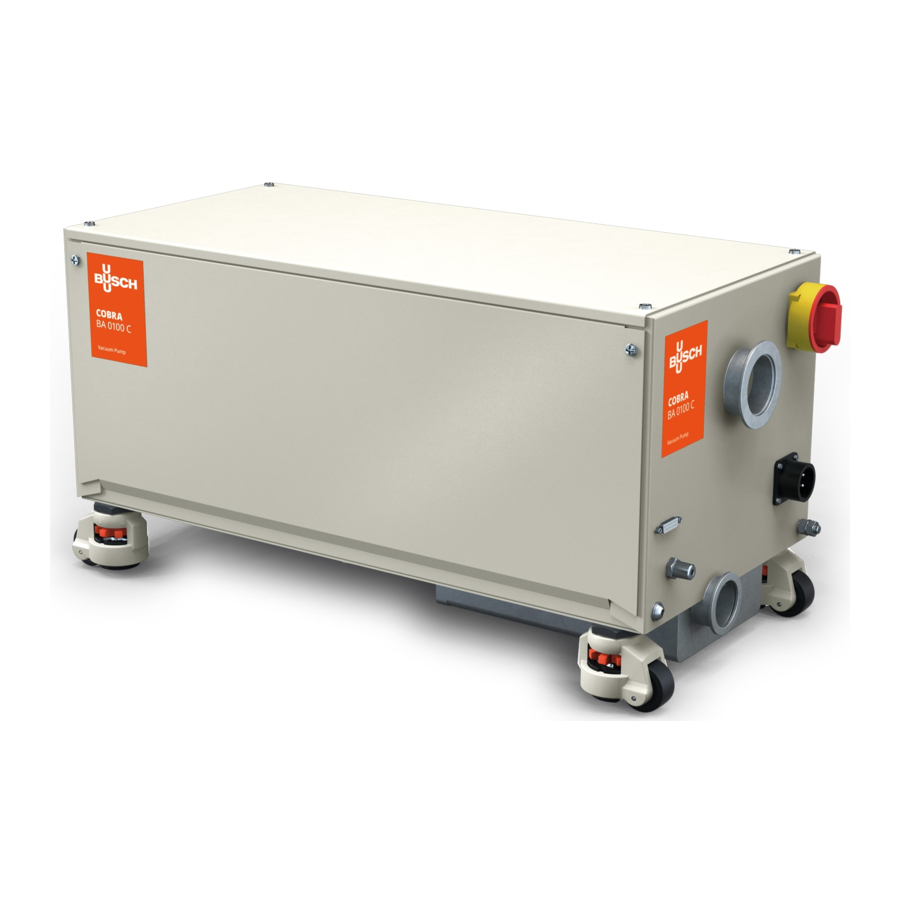
BUSCH COBRA BA 0100 C Instruction Manual
Dry screw vacuum pumps
Hide thumbs
Also See for COBRA BA 0100 C:
- Instruction manual (36 pages) ,
- Instruction manual (24 pages) ,
- Instruction manual (36 pages)

Related Manuals for BUSCH COBRA BA 0100 C


Summary of Contents for BUSCH COBRA BA 0100 C
- Page 1 Instruction Manual COBRA Dry Screw Vacuum Pumps BA 0100 C Ateliers Busch S.A. Zone industrielle, 2906 Chevenez Switzerland 2020/05/19 0870211637/-0003_en / Original instructions / Modifications reserved...
-
Page 2: Table Of Contents
Table of Contents Table of Contents 1 Safety.......................... 3 2 Product Description ....................4 2.1 Operating Principle ....................5 2.2 Application ......................5 2.3 Drive Variants ...................... 5 2.4 Standard Features....................5 2.4.1 Wheels......................5 2.4.2 Emergency Stop Switch................5 2.4.3 I/O and Communication Port (With VFD Only) .........5 2.4.4 Silencer.....................6 2.5 Optional Accessories................... -
Page 3: Safety
Safety Prior to handling the machine, this instruction manual should be read and understood. If anything needs to be clarified, please contact your Busch representative. Read this manual carefully before use and keep for future reference. This instruction manual remains valid as long as the customer does not change any- thing on the product. -
Page 4: Product Description
2 | Product Description Product Description ESS, MSH MC 4x WHL Axial fan I/O and communication port (with VFD only) Dilution gas valve (Optional) Eye bolt Earth connection (machine) Electrical data plate Emergency stop switch Inlet connection Mains connection Main switch Motor safety switch Nitrogen connection (Optional) Nameplate... -
Page 5: Operating Principle
Conveying of other media leads to an increased thermal and/or mechanical load on the machine and is permissible only after a consultation with Busch. The machine is intended for the placement in a non-potentially explosive environment. The machine is suitable for continuous operation but limited to a suction pressure of 150 hPa (mbar). -
Page 6: Silencer
3 | Transport 2.4.4 Silencer A silencer at the discharge connection (OUT) is provided as standard to reduce the exhaust gas noise. 2.5 Optional Accessories 2.5.1 Nitrogen System The nitrogen connection (NC) supplies nitrogen or clean dry compressed air for: –... -
Page 7: Storage
Storage | 4 Storage • Seal all apertures with adhesive tape or reuse provided caps. NOTICE Long storage time. Risk of damage to the machine! • Due to a long storage time the capacitors of the variable-frequency drive can lose efficiency because of electrochemical processes. -
Page 8: Connecting Lines / Pipes
• Install a suitable filter (5 micron or less) upstream from the machine. Connection size(s): – ISO-KF 50 If the machine is used as part of a vacuum system: • Busch recommends the installation of an isolation valve in order to prevent the machine from turning backwards. 5.2.2 Discharge Connection Connection size(s): –... -
Page 9: Nitrogen System Connection (Optional)
Installation | 5 5.2.3 Nitrogen System Connection (Optional) Dilution gas valve Nitrogen connection • Connect the nitrogen connection (NC) to the gas supply. Connection size: – G1/4, NPT (NC) + 2 adapters for pipe d6,15 and 6,5mm are supplied loose. To access the dilution gas valve (DGV): •... -
Page 10: Earth Connection
• Connect the earth connection of the machine (ECP). 5.4 Filling Oil NOTICE Use of an inappropriate oil. Risk of premature failure! Loss of efficiency! • Only use an oil type which has previously been approved and recommended by Busch. 10 / 24 0870211637_BA0100C_-0003_IM_en... - Page 11 Installation | 5 For oil type and oil capacity see Technical Data [► 22] and Oil [► 22]. Use a crussiform screwdriver Remove top cover Use a crussiform screwdriver Remove side cover Check oil level Oil sight glass 0870211637_BA0100C_-0003_IM_en 11 / 24...
-
Page 12: Electrical Connection
Change interval see instruction manual If there is no sticker (part no. 0565 568 959) on the machine: • Order it from your Busch representative. 5.5 Electrical Connection • Wire the mating connector (delivered loose) in accordance with the scheme below:... -
Page 13: Voltage Switch 208 - 400 V
Installation | 5 5.5.1 Voltage Switch 208 - 400 V • Make sure that the main switch (MSH) is in “OFF” position. • Select the needed voltage from the voltage switch (VS) (factory default setting ► 400 V). The 208 V setting is used for 200-240 VAC and the 400 V switch position is used for 380-480 VAC. -
Page 14: I/O And Communication Port Schematic (With Vfd Only)
6 | Commissioning 5.6 I/O and Communication Port Schematic (With VFD Only) Connector: D-Sub15, 15-pin, female Pin No. Description Signal User side Male connector Open: Stop Digital Input 2 Start pump Closed: Start 3 … 4 Power supply (max. 10 mA) 24 V OUT DI1 = 0 ►... -
Page 15: Conveying Condensable Vapours
Commissioning | 6 • Make sure that the installation conditions (see Installation Conditions [► 7]) are met. If the machine is equipped with a nitrogen system: • Turn on the nitrogen supply. • Switch on the machine. • Make sure that the maximum permissible number of starts does not exceed 6 starts per hour. -
Page 16: Maintenance
Risk of injuries! Risk of premature failure and loss of efficiency! • Respect the maintenance intervals or ask your Busch representative for service. • Shut down the machine and lock against inadvertent start up. If the machine is equipped with a barrier gas system: •... -
Page 17: Oil Level Inspection
If the oil becomes dark, white or looks different from the initial colour: • Change the oil immediately, see Oil Change [► 18]. You can consult your Busch representative in order to find out why this colour change has occurred. 0870211637_BA0100C_-0003_IM_en... -
Page 18: Oil Change
Risk of premature failure! Loss of efficiency! • Only use an oil type which has previously been approved and recommended by Busch. Drain pan For oil type and oil capacity see Technical Data [► 22] and Oil [► 22]. Use a crussiform screwdriver... -
Page 19: Overhaul
• Decontaminate the machine as much as possible and state the contamination status in a ‘Declaration of Contamination’. Busch will only accept machines that come with a completely filled in and legally bind- ing signed ‘Declaration of Contamination’. (Form downloadable from www.buschvacuum.com) -
Page 20: Decommissioning
• The exclusive use of Busch genuine spare parts and consumables is recommended for the correct functioning of the machine and to validate the warranty. There is no standard spare parts kits available for this product, if you require Busch genuine parts: •... -
Page 21: Troubleshooting
• Seek advice from your local Busch representa- tive. Measurement method or • Check the gauge, check reading is false. ultimate pressure directly at isolated inlet connec- tion. -
Page 22: Technical Data
12 | Technical Data 12 Technical Data BA 0100 C Nominal pumping speed (50Hz / 60Hz) m³/h 85 / 105 105* Ultimate pressure hPa (mbar) abs. 0.01 Torr 0.0075 Max. continuous suction pressure hPa (mbar) abs. Torr 112.5 Max. allowable discharge pressure hPa (mbar) rel. -
Page 23: Eu Declaration Of Conformity
14 EU Declaration of Conformity This Declaration of Conformity and the CE-mark affixed to the nameplate are valid for the machine within the Busch scope of delivery. This Declaration of Conformity is issued under the sole responsibility of the manufac- turer. - Page 24 Chile Israel Portugal United Arab Emirates info@busch.cl service_sales@busch.co.il busch@busch.pt sales@busch.ae China Italy Romania United Kingdom info@busch-china.com info@busch.it office@buschromania.ro sales@busch.co.uk Colombia Japan Russia info@buschvacuum.co info@busch.co.jp info@busch.ru info@buschusa.com Czech Republic Korea Singapore info@buschvacuum.cz busch@busch.co.kr sales@busch.com.sg www.buschvacuum.com 0870211637/-0003_en / © Ateliers Busch S.A.
Need help?
Do you have a question about the COBRA BA 0100 C and is the answer not in the manual?
Questions and answers