
Subscribe to Our Youtube Channel
Related Manuals for BUSCH COBRA DH Series


Summary of Contents for BUSCH COBRA DH Series
- Page 1 Operating Instructions COBRA DH 2760 | 4560 | 6260 | 2780 | 4580 |6280 Pumping station PU0116 | ed. A_en-US | Original 09/10/2024...
- Page 2 2 | 88 Operating Instructions COBRA DH 2760|4560|6260|2780|4580|6280 _ en-US...
-
Page 3: Table Of Contents
Table of contents Table of contents About this manual........................Validity............................1.1.1 Applicable documents....................1.1.2 Variants........................Target group..........................Conventions..........................1.3.1 Instructions in the text....................1.3.2 Pictographs........................1.3.3 Labels on product....................... 1.3.4 Abbreviations......................Safety............................General safety information....................Safety instructions........................Safety precautions........................Limits of use..........................Proper use.......................... - Page 4 Table of contents 6.3.5 Data types........................Connect to web interface......................6.4.1 Connecting web interface via factory pre-set DHCP network configuration..6.4.2 Connecting web interface via factory pre-set static IP address......6.4.3 Connect web interface via user-defined IP address.........."Ethernet" (LAN) connector....................Parameter set..........................
- Page 5 Recycling and disposal....................... 12.1 General disposal information....................Malfunctions..........................13.1 General............................13.2 Troubleshooting........................13.3 Error codes..........................Busch Group service solutions....................Ordering spare part packages....................Technical data and dimensions....................16.1 General............................16.2 Substances in contact with media..................16.3 Technical data.......................... 16.4 Dimensions..........................
-
Page 6: List Of Tables
List of tables List of tables Tbl. 1: Labels on product Tbl. 2: Abbreviations used Tbl. 3: Permissible ambient conditions Tbl. 4: COBRA DH | Combining components Tbl. 5: Requirements on the cooling water composition Tbl. 6: Required properties of the power supply cable Tbl. -
Page 7: List Of Figures
List of figures List of figures Fig. 1: Position of the labels on the product Fig. 2: COBRA DH Pumping station Fig. 3: COBRA DH Dashboard Fig. 4: Transporting pumping station with fork lift truck Fig. 5: Side panel removed Fig. -
Page 8: About This Manual
A component of these instructions Operating instructions of single pumps are not included in scope of delivery. Please download the respective manuals on the website of Busch for COBRA and on the website of Pfeiffer for HiLobe. 1.1.2 Variants These instructions apply to COBRA DH line pumping stations: ●... -
Page 9: Conventions
About this manual | 1 1.3 Conventions 1.3.1 Instructions in the text Usage instructions in the document follow a general structure that is complete in itself. The re quired action is indicated by an individual step or multi-part action steps. Individual action step A horizontal, solid triangle indicates the only step in an action. -
Page 10: Abbreviations
1 | About this manual Operating instructions note This sticker indicates that this operating instructions must be read before performing any tasks. Warning hot surface This label warns of injuries caused by high temperatures as a result of contact without protection during operation. Tbl. -
Page 11: Safety
Safety | 2 2 Safety 2.1 General safety information The following 4 risk levels and 1 information level are taken into account in this document. DANGER Immediately pending danger Indicates an immediately pending danger that will result in death or serious injury if not ob served. - Page 12 2 | Safety Risks during transport WARNING Risk of serious injury from swinging, toppling or falling objects During transport, there is a risk of crushing and impact on swinging, toppling or falling objects. There is a risk of injuries to limbs, up to and including bone fractures and head injuries. ►...
- Page 13 Safety | 2 WARNING Risk of crushing from rotating parts Fingers and hands may be caught by rotating pistons within the connection flange. This results in severe injuries. ► Keep limbs out of the reach of the roots pump. WARNING Risk of scalding from suddenly escaping hot cooling water The cooling water connections are open to both sides.
- Page 14 2 | Safety Risks during operation WARNING Danger of poisoning due to toxic process media escaping from the exhaust pipe During operation with no exhaust line, the vacuum pump allows exhaust gases and vapors to escape freely into the air. There is a risk of injury and fatality due to poisoning in processes with toxic process media.
-
Page 15: Safety Precautions
Safety | 2 WARNING Risk of crushing from rotating parts Fingers and hands may be caught by rotating pistons within the connection flange. This results in severe injuries. ► Keep limbs out of the reach of the roots pump. WARNING Health hazard through poisoning from toxic contaminated components or devices Toxic process media result in contamination of devices or parts of them. -
Page 16: Limits Of Use
2 | Safety Note Infringement of conformity due to modifications to the product The Declaration of Conformity from the manufacturer is no longer valid if the operator changes the original product or installs additional equipment. ● Following the installation into a system, the operator is required to check and re-evaluate the conformity of the overall system in the context of the relevant European Directives, be... -
Page 17: Personnel Qualification
Safety | 2 ● Pumping of corrosive media ● Pumping of condensing vapors ● Pumping of fluids ● Pumping of dust ● Operating with excessive irradiated heat output ● Operating in impermissible high magnetic fields ● Venting with impermissible high venting rates ●... - Page 18 2 | Safety ● Maintenance level 1 ─ Customer with technical education ─ Pfeiffer Vacuum service technician ● Maintenance level 3 ─ Pfeiffer Vacuum service technician 18 | 88 Operating Instructions COBRA DH 2760|4560|6260|2780|4580|6280 _ en-US...
-
Page 19: Product Description
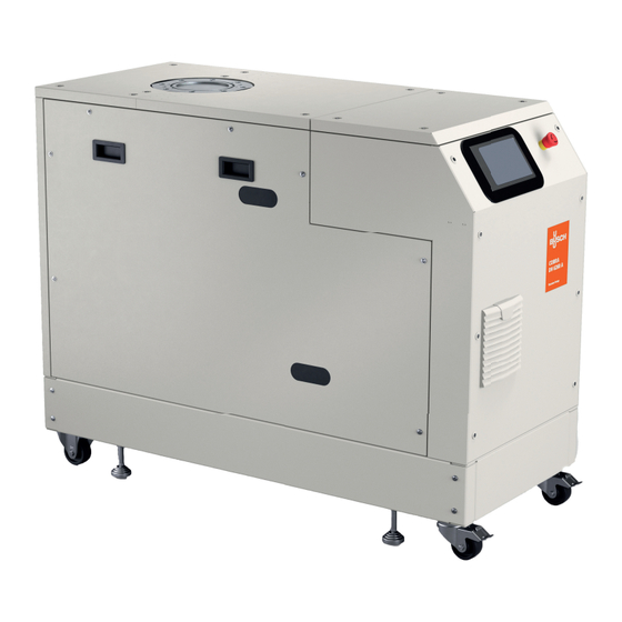
Product description | 3 3 Product description 3.1 Function The pumping stations in the COBRA DH model series are dry-compressing, fully integrated pump units. The station is designed as a mobile free-standing model; it consists of a roots pump and a backing pump specially matched to it. Fig. -
Page 20: Cooling
3.2 Identifying product To ensure unambiguous identification of the product when communicating with the Busch Group, always keep all of the information on the rating plate at hand. The following information is shown on the rating plates: ● Pump model ●... -
Page 21: Transportation And Storage
Transportation and Storage | 4 4 Transportation and Storage 4.1 Transporting the pumping station WARNING Danger of serious injury due to falling objects Due to falling objects there is a risk of injuries to limbs through to broken bones. ► Take particular care and pay special attention when transporting products manually. ►... -
Page 22: Store Pumping Station
4 | Transportation and Storage Fig. 4: Transporting pumping station with fork lift truck 1 Pumping station Fork arms Transporting pumping station with fork lift truck 1. Position the fork arms beneath the base frame. 2. You must take utmost care at all times when transporting the pumping station using a fork lift truck or a pallet truck. -
Page 23: Installation
Installation | 5 5 Installation 5.1 Preparing for set-up WARNING Danger to life from electric shock in the event of a fault In the event of a fault, devices connected to the mains may be live. There is a danger to life from electric shock when making contact with live components. -
Page 24: Filling With Lubricant
5 | Installation Note Screwing down adjustable feet at installation location Screw down the 4 adjustable feat at the installation location to avoid the pumping station rest ing on its rollers. 5.3 Filling with lubricant WARNING Danger of poisoning from toxic vapors Igniting and heating synthetic lubricants generates toxic vapors. -
Page 25: Fig. 6: Filling With Lubricant, Roots Pump
► Please refer to rating plate of the vacuum pump for type and quantity of intended lubricant. – Only the lubricant used during initial installation is permissible. ► Contact your Busch Group representative if you want to use another type of lubricant. Roots pump Required consumables ●... -
Page 26: Fig. 7: Filling With Lubricant, Backing Pump
5 | Installation 3. Hold the fill level limiter with the ring spanner and unscrew the drain screw at the same time. 4. Place a collection receptacle under each drain. 5. Fill the lubricant on both sides up to the maximum fill level. –... -
Page 27: Filling With Cooling Liquid
Installation | 5 5.4 Filling with cooling liquid Note Please note that the vacuum pumps are shipped pre-filled with cooling liquid. Filling with cool ing liquid should only be done if the vacuum pump is not already pre-filled. Required consumables ● Cooling liquid (Zitrec M 25), see Technical Data for quantity Required tool ●... -
Page 28: Connecting The Vacuum Side
5 | Installation 5.5 Connecting the vacuum side WARNING Risk of crushing from rotating parts Fingers and hands may be caught by rotating pistons within the connection flange. This results in severe injuries. ► Keep limbs out of the reach of the roots pump. NOTICE Property damage from intake of solid particles During commissioning, there is a risk of damage to the suction chamber from dirt from the sys... -
Page 29: Connecting Accessories
Installation | 5 Parameter Cooling water Water hardness < 5° dH (Germany) < 9° fH (France) < 1.25° e (England) < 90 mg/kg CaCO3 (USA) Appearance ● filtered ● mechanically clear ● visually clear ● no turbidity ● no sediment ●... -
Page 30: Connecting To Mains Power Supply
5 | Installation 5.9 Connecting to mains power supply DANGER Danger to life from electric shock Touching exposed and voltage-bearing elements causes an electric shock. Improper connec tion of the mains supply leads to the risk of touchable live housing parts. There is a risk to life. ►... -
Page 31: Interfaces
Interfaces | 6 6 Interfaces 6.1 "Remote" interface NOTICE Property damage on the electronics Separating all plug-and-socket connections within the bus system with voltage supply switched on may lead to the destruction of electronic components. ► Always disconnect the voltage supply before removing the connecting plug. ►... -
Page 32: Inputs
6 | Interfaces ● PLC High level: +13 V to +33 V ● PLC Low level: -33 V to +7 V ● Ri: 7 kΩ ● I < 200 mA 6.1.2 Inputs The digital inputs switch various electronic drive unit functions. Inputs are assigned with func tions ex-factory. -
Page 33: Using Rs-485 Interface
Interfaces | 6 6.2 Using RS-485 interface DANGER Danger to life from electric shock When establishing the voltages that exceed the specified safety extra-low voltage (according to IEC 60449 and VDE 0100), the insulating measures will be destroyed. There is a danger to life from electric shock at the communication interfaces. -
Page 34: Pfeiffer Vacuum Protocol For Rs-485 Interface
6 | Interfaces Networking as RS-485 bus The group address for the electronic drive unit is 902. 1. Install the devices according to the specification for RS-485 interfaces. 2. Make sure that all devices connected to the bus have different RS-485 device addresses [P:797]. -
Page 35: Telegram Example 2
Interfaces | 6 Data response: 633 Hz Current rotation speed (parameter [P:309], device address: "123") --> ASCII 6.3.4 Telegram example 2 Control command Switch on the pumping station (parameter [P:010], device address: "042" --> ASCII Control command understood Switch on the pumping station (parameter [P:010], device address: "042" -->... -
Page 36: Connecting Web Interface Via Factory Pre-Set Dhcp Network Configuration
6 | Interfaces Default network settings of the COBRA DH pumping station ● DHCP ● DHCP fallback ● The HiCube Neo falls back to its static IP address if the connected network does not have a DHCP server (router). ● Default IP address: 192.168.1.100 ●... -
Page 37: Ethernet" (Lan) Connector
Interfaces | 6 Procedure 1. Type the user-defined IP address of the COBRA DH into the browser address bar. 2. Press Enter. – The browser connects to the COBRA DH pumping station and the Dashboard appears. 6.5 "Ethernet" (LAN) connector The "Ethernet" connector enables direct communication with the unit via a computer in addition to standard control via the display. -
Page 38: Parameter Set
7 | Parameter set 7 Parameter set 7.1 General Important settings and function-related characteristics are factory-programmed into the electron ic drive unit as parameters. Each parameter has a three-digit number and a description. The pa rameter can be accessed via Pfeiffer Vacuum control units or externally via RS-485 using Pfeiffer Vacuum protocol. -
Page 39: Tbl. 11: Parameter Set | Control Commands
Parameter set | 7 Pa Parameter Designations Ac Data De Functions rame name cess type fault P035 Cfg Acc A1 Configuration ac 0 = Sealing gas valve cessory connec 1 = Purge valve tion A1 2 = Exhaust gas pump 3 = Cooling gas valve 6 = always 0 7 = always 1... -
Page 40: Status Requests
7 | Parameter set 7.3 Status requests Parame Indicator Designations Component Access Unit Data type type P303 Error code Error code P306 SetSpdAtt Set rotation speed reached Booster P308 SetRotSpd Set rotation speed Booster P309 ActualSpd Actual speed Booster P310 DrvCurrent Drive current Booster P312... -
Page 41: Reference Value Inputs
Parameter set | 7 Parame Indicator Designations Component Access Unit Data type type P379 NomSpdBKP Nominal rotation speed Backing pump P380 TempPwrBKP Temperature power stage Backing °C pump P381 TempExhBKP Current exhaust gas temperature Backing °C pump P382 TempOilBKP Current oil temperature Backing °C pump... -
Page 42: Additional Parameters For The Control Unit
7 | Parameter set Pa Indicator Designations Com Ac Unit Data min. max. de rame po cess type fault nents type P776 ASCurrOn Switch-on threshold backing pump for auto standby P797 RS485Adr RS-485 Interface ad dress Tbl. 13: Parameter set | Reference value inputs 7.5 Additional parameters for the control unit Note Additional parameters in the control unit... -
Page 43: Operation
Operation | 8 8 Operation NOTICE Damage to the device due to unintended operation Unintended operation can result in damage to the device. ► To ensure correct settings, ensure that the operating instructions are available to qualified personnel and operators. 8.1 Dashboard The dashboard appears automatically when you switch on the COBRA DH pumping station. -
Page 44: Main Menu
8 | Operation 8.2 Main menu Fig. 15: Main menu view for COBRA DH 1 Dashboard Help 2 Trend menu Date and time 3 Settings Language selection (DE/EN) 4 Devices Profile 5 Messages Navigating to other items from main menu ► Navigate from the main menu to: ●... -
Page 45: Vacuum Monitor
Operation | 8 8.4 Vacuum monitor Fig. 17: Calling up the Info panel 1 Calling up the Info panel Vacuum monitor The vacuum monitor shows the status information of the individual components as a graphical display. Calling up the Info panel ►... -
Page 46: Switching Pumping Station On/Off
8 | Operation Fig. 19: Parameters in the vacuum monitor Navigating to parameters ► Tap on the individual components in the vacuum monitor to navigate to the parameters of a unit on the dashboard. 8.5 Switching pumping station on/off WARNING Risk of cuts on moving, sharp-edged parts when reaching into the open high vacuum flange With the high vacuum flange open, access to sharp-edged parts is possible. -
Page 47: Fig. 20: Pumping Station In Operation
Operation | 8 Prerequisite ● Vacuum chamber connected on the HV side Fig. 20: Pumping station in operation 1 Display indicating pumping station in operation Status of the components during opera tion 2 Actual rotation speed Start pumping station 1. Tap the Dashboard button in the main menu. 2. -
Page 48: Trends
8 | Operation 8.6 Trends Fig. 22: Trend overview page COBRA DH 1 [P1] Drive current display (drive cur [P2] Drive current display (drive current) rent) 2 [P1] Drive voltage display (drive volt [P1] Current oil temperature display (current oil age) temperature) 3 [P1] Drive power display (drive pow... -
Page 49: Viewing Details Of A Trend
Operation | 8 5. Tap [Add Parameter] to finish the procedure. 6. Tap [Cancel] to cancel the procedure. Fig. 24: Deleting trends Deleting trends 1. Tap the Edit Trend Dashboard button to edit the dashboard. – You see an overview of all the added trends. 2. -
Page 50: Device Management
8 | Operation Viewing detailed value ► Tap on the required time in the trend overview to view the exact value for this time. 8.7 Device management Fig. 27: Device overview screen 1 Component displays Calling up overview page ► Tap on the Devices button in the main menu to access the overview page for all the added devices. -
Page 51: Editing And Filtering Detailed Information
Operation | 8 Fig. 29: Adding new device 1 Displaying device information Adding new device 1. Enter the name of the device in the search box. 2. Select the desired device. 3. Click [Submit]. 8.7.2 Editing and filtering detailed information Fig. 30: Parameter list of a device 1 Pumpstation Error code... -
Page 52: Help Page
8 | Operation Viewing and editing detailed information 1. Tap the name of the desired device to view its detailed information. 2. Edit the desired parameter or parameters. 3. Tap [Submit] to apply the changes. Fig. 32: Filtering parameter list by code/name 1 Input field for code/name for parameters Search results Filtering parameter list by Pfeiffer Vacuum code/name... -
Page 53: Settings
Operation | 8 8.9 Settings 8.9.1 General settings Fig. 34: General settings 1 Time/timezone display 2 Lock screen 3 Reset to factory settings 4 System restart Updating system time ► Tap [Time] to set the time and date. ► Tap [Timezone] to set the timezone. –... -
Page 54: Converting Units
8 | Operation 8.9.3 Converting units Fig. 36: Overview of units 1 Temperature Frequency 2 Pressure Converting units 1. Tap the Settings button in the main menu. 2. Tap [Units]. 3. Select a suitable unit in the drop-down menu. 8.10 Updating firmware via the cloud Prerequisites ●... -
Page 55: Update Procedure
Operation | 8 8.10.2 Update procedure Fig. 38: Update procedure The update starts automatically after uploading the firmware. Switching the device off during the update can lead to loss of data or to the update action being canceled. You will see a message once the update is complete. -
Page 56: User Maintenance
8 | Operation 8.11 User maintenance Fig. 40: Overview of all users 1 User Service user 56 | 88 Operating Instructions COBRA DH 2760|4560|6260|2780|4580|6280 _ en-US... -
Page 57: Operation
Operation | 9 9 Operation 9.1 Commissioning vacuum pump WARNING Danger of poisoning due to toxic process media escaping from the exhaust pipe During operation with no exhaust line, the vacuum pump allows exhaust gases and vapors to escape freely into the air. There is a risk of injury and fatality due to poisoning in processes with toxic process media. -
Page 58: Setting Supply Pressure Of Auxiliary Gas System (Optional)
9 | Operation 9.3 Setting supply pressure of auxiliary gas system (optional) Fig. 41: Setting supply pressure of auxiliary gas system 1 Pressure regulator Pressure reading Setting supply pressure of auxiliary gas system 1. Remove the left side panel. 2. Open the sealing gas supply on the gas cylinder. 3. -
Page 59: Setting Dilution Gas Flow (Optional)
Operation | 9 9.4 Setting dilution gas flow (optional) Fig. 42: Setting dilution gas flow 1 Flow meter Setting dilution gas flow 1. Remove the side panel. 2. Connect the dilution gas connection (DGC) to the gas supply. – Connection size: G1/4, ISO 228-1 Gas type Dry nitrogen or air Gas temperature... -
Page 60: Stand-By Operation
9 | Operation Setting parameters of backing pump 1. Set parameter [P:002] and [P:026]to "0". 2. Query the actual rotation speed of the backing pump via parameter [P:371]. 3. Set the desired rotation speed of the backing pump via parameter [P:766]. 9.5.2 Stand-by operation Note Permissible rotation speed range of the vacuum pump... -
Page 61: Operation Monitoring
Operation | 9 9.6 Operation monitoring 9.6.1 Temperature monitoring Depending on the sensor type, temperature thresholds for warning and malfunction messages are stored immutably in the parameter set of the electronic drive unit. If a measured value ex ceeds the threshold, the vacuum pump is switched to a safe state. Warnings ●... - Page 62 9 | Operation Procedure with clean processes You can switch off the vacuum pump in every pressure range, between atmospheric pressure and ultimate pressure directly after the process end. 1. Close the shut-off valve in the vacuum line and disconnect the vacuum pump from the proc ess.
-
Page 63: Maintenance
Maintenance | 10 10 Maintenance 10.1 Maintenance information WARNING Danger to life from electric shock during maintenance and service work There is a danger to life from electric shock when making contact with live components that still exist after the vacuum pump has been switched off. ►... -
Page 64: Checklist For Inspection And Maintenance
10 | Maintenance 10.3 Checklist for inspection and maintenance Note Maintenance frequency and service lives Maintenance frequency and service lives are process-dependent. Chemical and thermic loads or contamination reduce the recommended reference values. ● Determine the specific service lives during the first operating interval. ●... -
Page 65: Switching Pumping Station Off
Maintenance | 10 10.4 Switching pumping station off Note Before carrying out any work, safely disconnect device from mains 1. Shut down the device. 2. Wait until all components are at a complete standstill. 3. Switch off the master switch. 4. Disconnect the mains cable from the device. Fig. -
Page 66: Draining Lubricant
10 | Maintenance CAUTION Scalding from hot lubricant Danger of scalding when draining lubricant if it comes into contact with the skin. ► Wear protective equipment. ► Use a suitable collection receptacle. Note Pfeiffer Vacuum recommends determining the precise service life of the lubricant in the first operating year. -
Page 67: Fig. 45: Drain The Lubricant, Backing Pump
Maintenance | 10 Drain the lubricant, roots pump Note Unscrew the fill level limiter To drain the lubricant, in addition to the drain screw, also unscrew the fill level limiter on the pump bottom side. 1. Make sure that there is sufficient space underneath the vacuum pump to place a collection receptacle for the lubricant. -
Page 68: Filling With Lubricant
10 | Maintenance 10.5.2 Filling with lubricant WARNING Danger of poisoning from toxic vapors Igniting and heating synthetic lubricants generates toxic vapors. Danger of poisoning if in haled. ► Observe the application instructions and precautions. ► Do not allow tobacco products to come into contact with the lubricant. NOTICE Property damage from using non-approved lubricant Attainment of product-specific performance data is not ensured. -
Page 69: Fig. 47: Filling With Lubricant, Roots Pump
► Please refer to rating plate of the vacuum pump for type and quantity of intended lubricant. – Only the lubricant used during initial installation is permissible. ► Contact your Busch Group representative if you want to use another type of lubricant. Roots pump Required consumables ●... -
Page 70: Changing Coolant
10 | Maintenance 5. Fill the lubricant on both sides up to the maximum fill level. – Once full, lubricant overfills the fill level limiter, and drips out of the drain hole. – Fill level is visible in the center of the sight glass. 6. -
Page 71: Fig. 49: Draining Coolant
Maintenance | 10 Required consumables ● Cooling liquid (Zitrec M 25), see Technical Data for quantity Required aids ● Collection receptacle ● Funnel (optional) Fig. 49: Draining coolant 1 Drain screw Draining coolant 1. Use a fork lift truck to lift the pumping station. 2. -
Page 72: Cleaning Or Replacing Air Filter
10 | Maintenance Fig. 50: Filling with cooling liquid 1 Filler screw Vent screw Filling with cooling liquid 1. Unscrew the filler screw. 2. Unscrew the venting screw. 3. Fill up with cooling liquid to the top of the vent orifice. 4. -
Page 73: Fig. 51: Cleaning Or Replacing Air Filter
Maintenance | 10 Fig. 51: Cleaning or replacing air filter 1 Filter mat Ventilation grille Cleaning or replacing air filter 1. Carefully lever off the louver grille using a screwdriver. 2. Remove the filter mat. 3. Clean or replace the filter mat. 4. -
Page 74: Decommissioning
11 | Decommissioning 11 Decommissioning 11.1 Shutting down for longer periods Before shutting down the vacuum pump, observe the following instructions to adequately protect the interior of the vacuum pump (suction chamber) from corrosion: Procedure for a longer downtime of the vacuum pump (> 1 year) 1. -
Page 75: Recycling And Disposal
Recycling and disposal | 12 12 Recycling and disposal WARNING Health hazard through poisoning from toxic contaminated components or devices Toxic process media result in contamination of devices or parts of them. During maintenance work, there is a risk to health from contact with these poisonous substances. Illegal disposal of toxic substances causes environmental damage. -
Page 76: Malfunctions
13 | Malfunctions 13 Malfunctions 13.1 General WARNING Danger to life from electric shock in the event of a fault In the event of a fault, devices connected to the mains may be live. There is a danger to life from electric shock when making contact with live components. ►... -
Page 77: Error Codes
Err001 Emergency stop ● Emergency stop is confirmed ● Unlock emergency stop ● Error in the frequency converter ● Contact your Busch Group (FC) representative Err002 Motor excess voltage ● Error in the frequency converter ● Contact your Busch Group... - Page 78 Problem Possible causes Remedy code Err107 Overloading of the FC Roots ● Error in the frequency converter ● Contact your Busch Group Pump (FC) representative Err108 Overloading of the FC Back ● Error in the frequency converter ● Contact your Busch Group...
-
Page 79: Tbl. 22: Warning Messages Of The Pumping Station
Malfunctions | 13 Error Problem Possible causes Remedy code Wrn030 Pre-alarm: Excess temperature Roots ● Insufficient cooling ● Check the cooling Pump, Temperature Oil1 loose bearing side Wrn031 Pre-alarm: Excess temperature Roots ● Insufficient cooling ● Check the cooling Pump, Temperature Oil2 fixedbearing side Wrn032 Pre-alarm: Excess temperature Roots... -
Page 80: Busch Group Service Solutions
14 | Busch Group service solutions 14 Busch Group service solutions To resolve problems not listed in the troubleshooting table, please contact your Busch Group rep resentative. 80 | 88 Operating Instructions COBRA DH 2760|4560|6260|2780|4580|6280 _ en-US... -
Page 81: Ordering Spare Part Packages
Spare part package COBRA NS There are no standard spare part packages for this product. If you require Busch original parts: ● Please contact your Busch Group representative. Spare part packages Order number VSC 100 (standard operating fluid), 1 L... -
Page 82: Technical Data And Dimensions
16 | Technical data and dimensions 16 Technical data and dimensions 16.1 General Basis for the technical data of Pfeiffer Vacuum roots pumps ● Specifications according to PNEUROP committee PN5 ● ISO 21360-1: 2016 “Vacuum technology - Standard methods for measuring vacuum-pump performance - General description”... -
Page 83: Technical Data
Technical data and dimensions | 16 16.3 Technical data Type designation COBRA DH 2760 COBRA DH 4560 COBRA DH 6260 Part number PP S50 002 PP S50 004 PP S50 006 Connection flange (in) DN 160 ISO-F | DN 150 DN 160 ISO-F | DN 150 DN 160 ISO-F | DN 150 PN 16 PN 16... - Page 84 16 | Technical data and dimensions Type designation COBRA DH 2780 COBRA DH 4580 COBRA DH 6280 Cooling water flow, min. 14 l/min 14 l/min 14 l/min Input voltage(s) 380 – 480 V AC (±10 %), 380 – 480 V AC (±10 %), 380 –...
-
Page 85: Dimensions
Technical data and dimensions | 16 16.4 Dimensions G asinlet 1075 1446 Fig. 52: Dimensions COBRA DH 2760 | 4560| 6260 | 2780 | 4580 | 6280 Dimensions in mm Operating Instructions COBRA DH 2760|4560|6260|2780|4580|6280 _ en-US 85 | 88... -
Page 86: Ec Declaration Of Conformity
EC Declaration of Conformity Declaration for product(s) of the type: Pumping station COBRA DH 2760 COBRA DH 4560 COBRA DH 6260 COBRA DH 2780 COBRA DH 4580 COBRA DH 6280 We hereby declare that the listed product satisfies all relevant provisions of the follow ing European Directives. -
Page 87: Declaration Of Conformity
UK Declaration of Conformity This declaration of conformity has been issued under the sole responsibility of the manufacturer. Declaration for product(s) of the type: Pumping station COBRA DH 2760 COBRA DH 4560 COBRA DH 6260 COBRA DH 2780 COBRA DH 4580 COBRA DH 6280 We hereby declare that the listed product satisfies all relevant provisions of the follow... - Page 88 With a network of over 60 companies in more than 40 countries and agencies worldwide, Busch has a global presence. In every country, highly competent local personnel delivers custom-tailored support backed by a global network of expertise. Wherever you are.
Need help?
Do you have a question about the COBRA DH Series and is the answer not in the manual?
Questions and answers