AUMA GK 10.2 Operation Instructions Manual
Multi-turn gearboxes
Hide thumbs
Also See for GK 10.2:
- Manual (20 pages) ,
- Operation instructions manual (24 pages) ,
- Operation instructions manual (8 pages)

Subscribe to Our Youtube Channel
Related Manuals for AUMA GK 10.2


Summary of Contents for AUMA GK 10.2
- Page 1 Multi-turn gearboxes GK 10.2 GK 40.2 Operation instructions Assembly and commissioning...
-
Page 2: Table Of Contents
Servicing and maintenance....................7.1. Preventive measures for servicing and safe operation 7.2. Maintenance intervals 7.3. Disposal and recycling Technical data......................... 8.1. Technical data Multi-turn gearboxes Spare parts..........................9.1. Multi-turn gearboxes GK 10.2 GK 25.2 9.2. Multi-turn gearboxes GK 30.2 GK 40.2 Index............................ -
Page 3: Safety Instructions
GK 10.2 GK 40.2 Safety instructions Safety instructions 1.1. Basic information on safety Our products are designed and manufactured in compliance with recognised Standards/directives standards and directives. This is certified in a Declaration of Incorporation and an EU Declaration of Conformity. -
Page 4: Range Of Application
Any device modification requires prior written consent of the manufacturer. 1.2. Range of application AUMA multi-turn gearboxes are designed for the operation of industrial valves, e.g. gate valves and globe valves. Other applications require explicit (written) confirmation by the manufacturer. -
Page 5: Short Description
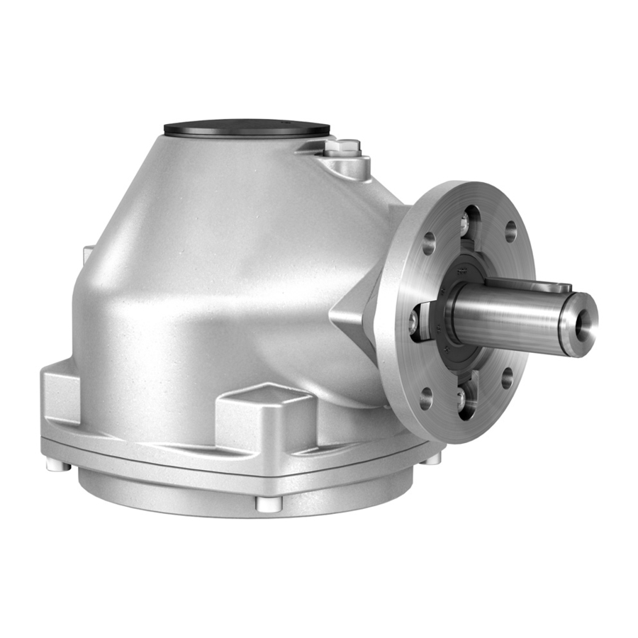
GK 40.2 Short description Short description AUMA bevel gearboxes are multi-turn gearboxes transmitting a rotary movement to the valve. They are driven either via electric motor (by means of a multi-turn actuator) or manually (via a handwheel). The drive axle is perpendicular to the output axle, thus adjusting in a single stage... -
Page 6: Name Plate
Approval plate in explosion-proof version Additional plate, e.g. KKS plate (Power Plant Classification System) Description of gearbox name plate Figure 2: Gearbox name plate (example of GK 10.2) Name of manufacturer Address of manufacturer Type designation - valve attachment (flange) - Page 7 Dust explosion protection Data Matrix code When registered as authorised user, you may use our AUMA Assistant App to scan the Data Matrix code and directly access the order-related product documents without having to enter order number or serial number.
- Page 8 GK 40.2 Name plate of rotation e.g. for a counterclockwise closing valve, a AUMA reversing gearbox of the GW 14.1 type can be mounted between multi-turn actuator and bevel gearbox. From size GK 30.2, the direction of rotation can be selected when ordering. For these sizes, the direction of rotation is marked on the order-related technical data sheet as "CCW"...
-
Page 9: Transport And Storage
A and AF when leaving the factory. Suspension is always performed using lifting straps /round slings wound around the gearbox mounting flange and the actuator housing. Figure 7: Example of GK 10.2, horizontal suspension GK 25.2 Actuators for GK 25.2 gearbox are always supplied separately when leaving the factory. - Page 10 GK 10.2 GK 40.2 Transport and storage Figure 8: Example of GK 25.2, horizontal suspension and mounted actuator GK 30.2 Actuators for the GK 30.2 gearbox are always supplied separately when leaving the factory and must be transported and lifted separately. Unless specified otherwise by the customer, output drive types A and AF are mounted to the gearbox.
- Page 11 GK 10.2 GK 40.2 Transport and storage Figure 10: Example of GK 40.2, horizontal and vertical suspension Horizontal suspension Vertical suspension Table 2: Gearbox weight with output drive sleeve (without bore) and grease filling in the gear housing Gewicht [kg] GK 10.2...
-
Page 12: Storage
GK 10.2 GK 40.2 Transport and storage Weights for output drive type AF 30.2 AF 35.2 AF 40.2 For the actuator and actuator controls weights, refer to the respective operation instructions. 4.2. Storage Danger of corrosion due to inappropriate storage! Store in a well-ventilated, dry room (maximum humidity 70 %). -
Page 13: Assembly
This chapter supplies basic information and instructions which should be heeded in addition to the operation instructions of the multi-turn actuator. When delivered with AUMA multi-turn actuators, the multi-turn actuator-gearbox Mounting positions combination is delivered in the ordered mounting position up to size GK 16.2. For packing reasons, multi-turn actuator and gearbox will be delivered separately from size GK 25.2. - Page 14 SA 16.2 Standard flange according to EN ISO 5210 Screws to multi-turn ac- Screws are included in the scope of delivery of the gearbox for mounting AUMA multi-turn actuators. When mounting other multi-turn actuators, the screws might be tuator either too long or too short (insufficient reach of screws).
-
Page 15: Mount Gearbox To Valve
GK 10.2 GK 40.2 Assembly Screws which are too long could make contact with the housing parts, presenting the risk that the multi-turn actuator performs a radial shift with respect to the gearbox. This can lead to shearing of the screws. -
Page 16: Output Drive Type A
GK 10.2 GK 40.2 Assembly 5.4.2. Output drive type A Figure 14: Output drive type A (example of A 10.2) Output mounting flange Stem nut Valve stem Output drive type A consisting of output mounting flange [1] with axial bearing stem Short description nut [2]. -
Page 17: 5.4.2.2. Stem Nut For Output Drive Type A: Finish Machining
5.4.2.2. Stem nut for output drive type A: finish machining This working step is only required if stem nut is supplied unbored or with pilot bore. Information For exact product version, please refer to the order-related technical data sheet or the AUMA Assistant App. - Page 18 GK 10.2 GK 40.2 Assembly Figure 17: Example of output drive A 10.2 Stem nut Axial needle roller bearing [2.1] Axial bearing washer [2.2] Axial needle roller and cage assembly Spigot ring How to proceed Remove spigot ring [3] from output drive.
-
Page 19: Output Drive Types B/C/D And E
GK 10.2 GK 40.2 Assembly 5.4.3. Output drive types B/C/D and E Figure 18: Mounting principle Flange/gearbox Hollow shaft Output drive sleeve (illustration examples) Valve shaft (example with key) Connection between hollow shaft and valve via output drive sleeve fixed to the hollow Short description shaft of the gearbox via retaining ring. -
Page 20: 5.4.3.1. Gearbox With Output Drive Types B: Mount To Valve
GK 10.2 GK 40.2 Assembly 5.4.3.1. Gearbox with output drive types B: mount to valve Figure 19: Mounting output drive types B GK gearbox Valve Valve shaft Check if mounting flanges fit together. Check, if output drive of gearbox [2] matches the output drive of valve/valve shaft [2/3]. -
Page 21: Accessories For Assembly
GK 10.2 GK 40.2 Assembly 5.5. Accessories for assembly 5.5.1. Stem protection tube for rising valve stem Figure 20: Assembly of the stem protection tube Protective cap for stem protection tube (fitted) [1]* Option: Protective cap made of steel (screwed) -
Page 22: Commissioning
GK 10.2 GK 40.2 Commissioning Commissioning 6.1. Seating via multi-turn actuator This chapter supplies basic information and instructions which should be heeded in addition to the operation instructions of the multi-turn actuator. The valve manufacturer has to determine whether the valve is limit or torque seated. -
Page 23: Servicing And Maintenance
Therefore, we recommend contacting our service. Only perform servicing and maintenance tasks when the device is switched off. AUMA AUMA offers extensive service such as servicing and maintenance as well as Service & Support customer product training. For the contact addresses, refer to our website (www.auma.com). - Page 24 GK 10.2 GK 40.2 Servicing and maintenance Arrange for controlled waste disposal of the disassembled material or for sep- arate recycling according to materials. Observe the national regulations for waste disposal.
-
Page 25: Technical Data
Standard: Cylindrical with parallel key according to DIN 6885.1 Option: Square: tapered (according to DIN 3233) or cylindrical shape With respect to size, please contact AUMA Operation Motor operation With electric multi-turn actuator (maximum permissible input speed: 240 rpm) Manual operation... - Page 26 AUMA silver-grey (similar to RAL 7037) Option: Available colours on request Lifetime AUMA multi-turn gearboxes meet or exceed the lifetime requirements of EN 15714-2. Detailed information can be provided on request. Accessories Reversing gearboxes GW reversing gearbox for reversal of rotation direction for manual and motor operation...
-
Page 27: Spare Parts
GK 10.2 GK 40.2 Spare parts Spare parts 9.1. Multi-turn gearboxes GK 10.2 GK 25.2... - Page 28 Spare parts Please state device type and our order number (see name plate) when ordering spare parts. Only original AUMA spare parts should be used. Failure to use original spare parts voids the warranty and exempts AUMA from any liability. Representation of spare parts may slightly vary from actual delivery.
- Page 29 GK 10.2 GK 40.2 Spare parts 9.2. Multi-turn gearboxes GK 30.2 GK 40.2...
- Page 30 Spare parts Please state device type and our order number (see name plate) when ordering spare parts. Only original AUMA spare parts should be used. Failure to use original spare parts voids the warranty and exempts AUMA from any liability. Representation of spare parts may slightly vary from actual delivery.
-
Page 31: Index
GK 10.2 GK 40.2 Index Index Qualification of staff Accessories for assembly Range of application Ambient temperature 6, 26 Recycling Applications Reduction ratio Assembly Reversal of direction of rota- Assistant App tion AUMA Assistant App Reversing gearbox Commissioning 3, 22... - Page 32 AUMA Riester GmbH & Co. KG P.O. Box 1362 DE 79373 Muellheim Tel +49 7631 809 - 0 Fax +49 7631 809 - 1250 info@auma.com www.auma.com Y000.328/003/en/1.21 For detailed information on AUMA products, refer to the Internet: www.auma.com...
Need help?
Do you have a question about the GK 10.2 and is the answer not in the manual?
Questions and answers