
Related Manuals for Munters ATLAS 74


Summary of Contents for Munters ATLAS 74
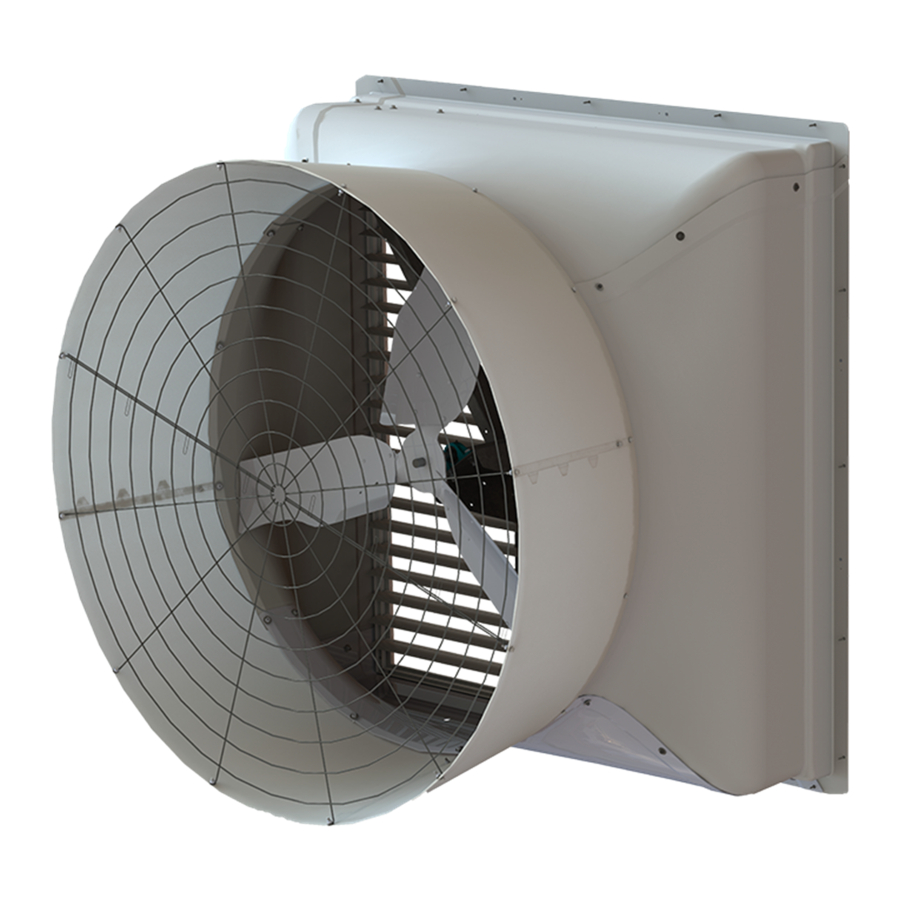
- Page 1 Munters ATLAS 74 Instruction Manual 74” Exhaust Fan ATLAS 74 Fan Models: ATS743F3CT-E • ATS743F3CT-P © Munters Corporation, July 2021 QM1095r1...
- Page 2 Instructions for Use and Maintenance Thank You: Thank you for purchasing an ATLAS 74 Fan. Munters equipment is designed to be the highest performing, highest quality equipment you can buy. With the proper installation and maintenance it will provide many years of service.
-
Page 3: Table Of Contents
2. Installation Instructions 8-12 Installation Cone Installation PT Shutter Shutter Wind Kit 15-16 3. Electrical Wiring 4. Operation 5. Maintenance 20-21 6. Winterizing Winterizing Winter Weather Protection 7. Troubleshooting 8. Exploded View and Parts List 24-25 © Munters Corporation, July 2021 QM1095r1... -
Page 4: Unpacking The Equipment
1 – Right Lift Bracket, PWDCTD 1 – Hardware Package as follows: HP1891 - for FH1890 Qty. Cat. No. Description KS1180 ⁄ ”-16 x 1.5” Flange Head Bolt, ZP KN0705 ⁄ ”-16 SRTD Flange Nut, ZP © Munters Corporation, July 2021 QM1095r1... -
Page 5: Fan Dimensions
4¾ " SIDE VIEW FRONT VIEW WALL OPENING K-Dia. DIA. (I.D., framed) 74” ⁄ ” 21 ⁄ ” 44 ⁄ ” 89” 89” ⁄ ” 35 ⁄ ” 60 ” 2⁵⁄₁₆” ⁄ ” 85”W 85”H © Munters Corporation, July 2021 QM1095r1... -
Page 6: Fan Spacing
3¾ " clearance for the Wind Kit Bracket to be installed. If the fans are to be installed side-by-side with the Wind Kit Brackets adjacent to each other, the minimum fan spacing is 98" Center-to-Center. See Figure Below. 98" Center-to-Center Top View 98" Center-to-Center 3¾ " ¼ " Elevation View © Munters Corporation, July 2021 QM1095r1... - Page 7 If the fans are to be installed closer, then the Wind Kit Brakcet for one fan should be offset 6" up or down from the previous fan, then the minimum fan spacing is 93" Center-to-Center. See Figure Below. 93" Center-to-Center Top View 93" Center-to-Center 3¾ " ¼ " Elevation View © Munters Corporation, July 2021 QM1095r1...
-
Page 8: Installation Instructions
Page 5) Concrete Stem Wall Building Columns - 20’-0” O.C. Figure 1A Building Column 4x4 Post or 2x Treated Framing (See Chart on Page 5) Concrete Stem Wall Building Columns - 25’-0” O.C. Figure 1B © Munters Corporation, July 2021 QM1095r1... - Page 9 Once fan has been installed in wall Lift Bracket can be removed and installed in next fan for installation. Nut [E] Bolt [D] Left Lift Bracket Right Lift Bracket Bearing Bracket Nut [E] Bolt [D] Figure 2 © Munters Corporation, July 2021 QM1095r1...
- Page 10 4" Minimum Framing for fan, Top and Sides Note: Once Fan is installed in wall, remove Lifting Brackets from Fan and install in next Fan for installation. 2" Minimum Framing for fan, Bottom Figure 3B Wall Framing © Munters Corporation, July 2021 QM1095r1...
-
Page 11: Cone Installation
At the inner pair of holes of each joint fasten using (1) Bolt [A] and Nut [B] with the bolt head on the side with the tabs. See Figure 5A. Nut [B] Bolt [A] Outer Hole Bolt [A] Inner Hole Nut [B] Figure 5A © Munters Corporation, July 2021 QM1095r1... - Page 12 Fasten cone to fan orifice using (12) Bolt [A], Washer [C] and Nut [B] with bolt and washer on inside of fan orifice and nut on outside of cone. See Figure 6. Hole in Fan Orifi ce Nut [B] Washer [C] Bolt [A] Figure 6 © Munters Corporation, July 2021 QM1095r1...
- Page 13 Insert guard into cone with the eyelets facing you. Install eyelets over (4) Bolts already installed at joints in cone and fasten with Nut [B]. Secure (8) remaining eyelets using Bolt [A] and Nut [B]. See Figure 8. Bolt [A] Nut [B] Previously installed - Bolt and Nut Nut [B] Figure 8 © Munters Corporation, July 2021 QM1095r1...
-
Page 14: Shutter
Step 10 Fasten shutter in place by rotating the side and top shutter clips over the shutter flanges. See Figure 10. ¼ " Position to install/remove Shutter Figure 10 Position to hold Shutter in place © Munters Corporation, July 2021 QM1095r1... -
Page 15: Shutter Wind Kit
'U' slot should be facing up and each Bracket should be mounted in same direction. See Figure 11A. Fasten Brackets in place using (2) Lag Screws (not provided). See Figure 11B. Figure 11A Wind Kit Bracket Lag Screw (not provided) Figure 11B © Munters Corporation, July 2021 QM1095r1... - Page 16 Slide the Wind Kit Pipe into the hole in the Left Wind Kit Bracket until it stops at the other side of the Bracket and set Pipe down into slot in opposite Bracket. See Figure 12A. For the completed Wind Kit installation See Figure 12B. Figure 12A Figure 12B © Munters Corporation, July 2021 QM1095r1...
-
Page 17: Electrical Wiring
For electrical connection requirements, refer to diagram on motor nameplate and to information enclosed with the Munters environmental control to be used. After wiring check for proper motor rotation. - Page 18 "Zip" tie the cable to strut to prevent cable from getting tangled in the pulley or belt. See Figure 14. Then run the cable out the drain hole to the circuit breaker or control panel. (Continued on next page). Figure 14 © Munters Corporation, July 2021 QM1095r1...
-
Page 19: Operation
Minimum operating frequency of 30 Hz. Moving Parts, Disconnect Will require three pole contractors with overload protection (by others). Power Before Servicing. WARNING Moving Parts: Disconnect Power Before Servicing. WARNING Do Not Power Wash Electrical Devices. © Munters Corporation, July 2021 QM1095r1... -
Page 20: Maintenance
Use no more than 2 shots when greasing fan. • A premium non-water based grease is recommended: Shell Alvania #2 - Mobil Mobilux #2 Exxon Unirex N2 - Texaco Premium RB Mobil 532 - Texaco Multifak #2 © Munters Corporation, July 2021 QM1095r1... - Page 21 Mark is at Mark 4 on the tensioner arm. See Figure 15B. Hold tensioner at this setting and tighten the 10mm bolt to 40 ft. lbs. Figure 15A [54 N-m] torque. Mark 4 Alignment Mark Figure 15B © Munters Corporation, July 2021 QM1095r1...
-
Page 22: Winterizing
Munters Product and System manufacturers recommendations. The supplier listing above is given Warranties do not cover cone or fan as a reference only. Munters does not endorse any specific snow guard product and no performance warranty is implied. damage from external sources. -
Page 23: Troubleshooting
3. Frequency drive improperly adjusted 3. See operation, Step 2 for adjustments guidelines Excessive 1. Tighten fasteners 1. Motor loose on mount Vibration 2. Replace propeller 2. Propeller damaged 3. Repair or replace motor or propeller shaft © Munters Corporation, July 2021 QM1095r1... -
Page 24: Exploded View And Parts List
Exploded View © Munters Corporation, July 2021 QM1095r1... - Page 25 PT74 PT74 Shutter, all plastic FA2619 FA2619 Wind Bracket, GZ AC1416 AC1416 Wind Pipe, GZ HP1162 HP1162 Hardware Pkg., Fan/Cone Install * Contact offi ce for replacement part numbers for your fan confi guration. © Munters Corporation, July 2021 QM1095r1...
- Page 26 Atlas 74 Fan with Cone is developed and produced by Munters Corporation, Lansing, Michigan U.S.A. 1-800-227-2376 Munters Europe AB, Isafjordsgatan 1, P.O. Box 1150, SE-164 26 Kista, Sweden. Phone +46 08 626 63 00, Fax +46 8 754 56 66.
Need help?
Do you have a question about the ATLAS 74 and is the answer not in the manual?
Questions and answers