Sony DCR-PC4E Service Manual

Sony DCR-PC4E Service Manual

Digital video camera recorder
Hide thumbs Also See for DCR-PC4E:
Table of Contents

Advertisement

DCR-PC4E/PC5/PC5E
SERVICE MANUAL
SERVICE MANUAL
Level 2
On the VC-245 board
This service manual provides the information that is premised the
circuit board replacement service and not intended repair inside the
VC-245 board.
Therefore, schematic diagram, printed wiring board and electrical parts
list of the VC-245 board are not shown.
The following pages are not shown.
Schematic diagram .......................... Pages 4-17 to 4-54
Printed wiring board ......................... Pages 4-55 to 4-58
Electrical parts list ............................ Pages 6-13 to 6-25
Ver 1.1 2003. 06
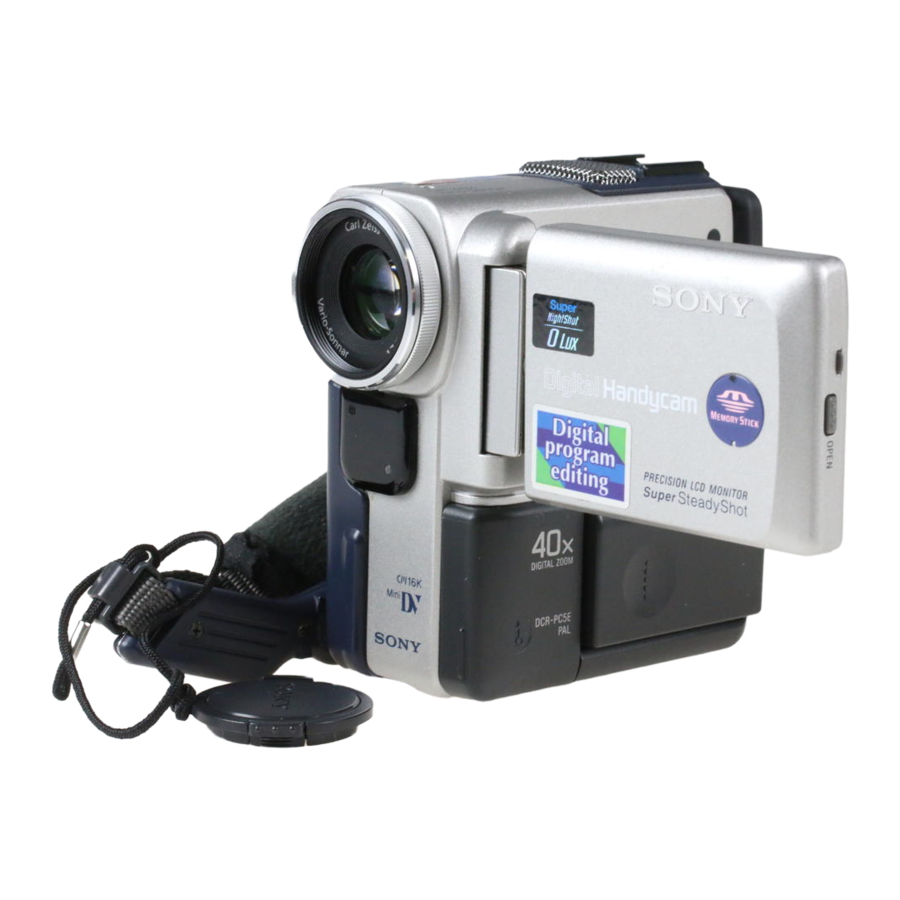
Photo : DCR-PC5 (GRAY)
RMT-811
For MECHANISM ADJUSTMENTS, refer to the
"DV MECHANICAL ADJUSTMENT MANUAL
J MECHANISM " (9-929-807-11).
DCR-PC5
DCR-PC4E/PC5E : PAL model
• Table showing differences is shown on page 3.
SPECIFICATIONS
DIGITAL VIDEO CAMERA RECORDER
RMT-809/811/812
US Model
Canadian Model
Korea Model
DCR-PC5
AEP Model
UK Model
DCR-PC4E/PC5E
Australian Model
Chinese Model
DCR-PC5E
E Model
Hong Kong Model
Tourist Model
DCR-PC5/PC5E
J MECHANISM
: NTSC model
— Continued on next page —

Advertisement

Table of Contents
loading
Need help?

Need help?

Do you have a question about the DCR-PC4E and is the answer not in the manual?

Questions and answers

Subscribe to Our Youtube Channel

Summary of Contents for Sony DCR-PC4E

  • Page 1 VC-245 board. DCR-PC5 : NTSC model Therefore, schematic diagram, printed wiring board and electrical parts DCR-PC4E/PC5E : PAL model list of the VC-245 board are not shown. The following pages are not shown. Schematic diagram ......Pages 4-17 to 4-54 Printed wiring board ......
  • Page 2 MARK 0 ON THE SCHEMATIC DIAGRAMS AND IN THE PARTS CRITIQUES POUR LA SÉCURITÉ DE FONCTIONNEMENT. NE LIST ARE CRITICAL TO SAFE OPERATION. REPLACE THESE REMPLACER CES COMPOSANTS QUE PAR DES PIÈSES SONY COMPONENTS WITH SONY PARTS WHOSE PART NUMBERS DONT LES NUMÉROS SONT DONNÉS DANS CE MANUEL OU APPEAR AS SHOWN IN THIS MANUAL OR IN SUPPLEMENTS DANS LES SUPPÉMENTS PUBLIÉS PAR SONY.
  • Page 3 Table for differences of function Model DCR-PC4E DCR-PC5 DCR-PC5E DCR-PC5E Remark Destination AEP, UK US, CND, E, AEP, UK E, AUS, HK, HK, KR, JE CN, JE Color system NTSC Remote commander RMT-809 RMT-811 RMT-812 RMT-811 40 × 120 ×...
  • Page 4: Table Of Contents

    Focusing manually ······························································· 1-15 BLOCK DIAGRAMS Advanced Playback Operations ··············································· 1-15 3-1. OVERALL BLOCK DIAGRAM (1/3)(DCR-PC4E) ······ 3-1 Playing back a tape with picture effects ······························ 1-15 3-2. OVERALL BLOCK DIAGRAM (1/3)(DCR-PC5/PC5E) · 3-3 Playing back a tape with digital effects ······························· 1-16 3-3.
  • Page 5 5-1. Flange Back Adjustment (1) ·········································· 5-19 Shematic diagram and printed wiring board of the 5-2. Flange Back Adjustment (2) ·········································· 5-19 VC-245 board are not shown. Flange Back Check ························································ 5-20 Pages from 4-17 to 4-58 are not shown. Optical Axis Adjustment ···············································...
  • Page 6 1-1. Preparations for Playback ·············································· 5-48 1-2. IC301 TRX (RF) PB BIST Check ································· 5-48 1-3. IC301 AUD (ABUS) PB BIST Check ··························· 5-48 1-4. IC301 VFD PB BIST Check ········································· 5-48 1-5. IC301 ENCODER BIST Check ···································· 5-50 1-6. Processing after Completing Playback System Check ·· 5-51 Recording System Check ··············································...
  • Page 7: Service Note

    SERVICE NOTE POWER SUPPLY DURING REPAIRS In this unit, about 10 seconds after power is supplied to the battery terminal using the regulated power supply (4.2V), the power is shut off so that the unit cannot operate. This following two methods are available to prevent this. Take note of which to use during repairs. Method 1.
  • Page 8: Self-Diagnosis Function

    SELF-DIAGNOSIS FUNCTION SELF-DIAGNOSIS FUNCTION SELF-DIAGNOSIS DISPLAY When problems occur while the unit is operating, the counter of the When problems occur while the unit is operating, the self-diagnosis function starts working, and displays on the viewfinder or LCD viewfinder or LCD screen consists of an alphabet and 4-digit screen what to do.
  • Page 9: Self-Diagnosis Code Table

    SELF-DIAGNOSIS CODE TABLE Self-diagnosis Code Block Detailed Symptom/State Correction Function Code Non-standard battery is used. Use the info LITHIUM battery. Condensation. Remove the cassette, and insert it again after one hour. Video head is dirty. Clean with the optional cleaning cassette. LOAD direction.
  • Page 10: General

    DCR-PC4E/PC5/PC5E SECTION 1 This section is extracted from instruction GENERAL manual. (DCR-PC4E/PC5E model)
  • Page 19 1-10...
  • Page 20 1-11...
  • Page 21 1-12...
  • Page 22 1-13...
  • Page 23 1-14...
  • Page 24 1-15...
  • Page 25 1-16...
  • Page 26 1-17...
  • Page 27 1-18...
  • Page 28 1-19...
  • Page 29 1-20...
  • Page 30 1-21...
  • Page 31 1-22...
  • Page 32 1-23...
  • Page 33 1-24...
  • Page 34 1-25...
  • Page 35 1-26...
  • Page 36 1-27...
  • Page 37 1-28...
  • Page 38 1-29...
  • Page 39 1-30...
  • Page 40 1-31...
  • Page 41 1-32...
  • Page 42 1-33...
  • Page 43 1-34...
  • Page 44 1-35...
  • Page 45 1-36...
  • Page 46 1-37...
  • Page 47 1-38...
  • Page 48 1-39...
  • Page 49 1-40...
  • Page 50 1-41...
  • Page 51 1-42...
  • Page 52 1-43...
  • Page 53 1-44E...
  • Page 54: Disassembly

    DCR-PC4E/PC5/PC5E SECTION 2 DISASSEMBLY The following flow chart shows the disassembly procedure. 2-1. LCD unit, PD-126 board PD-126 board service position 2-2. Cabinet (R) block assembly-1 Service position (Mainly for adjustment) 2-3. Cabinet (R) block assembly-2 2-4. BJ-1 board 2-5. Lens-EVF block assembly 2-9.
  • Page 55: Lcd Unit, Pd-126 Board

    NOTE: Follow the disassembly procedure in the numerical order given. 2-1. LCD UNIT, PD-126 BOARD REMOVING THE PD-126 BOARD, LCD cabinet (R) Two screws (M1.7 × 2.5), assembly INVERTER TRANSFORMER UNIT lock ace, p2 4 Back light Cold cathode 0 Screw (M1.7 × 2.5), 3 Remove the fluorescent tube lock ace, p2...
  • Page 56: Cabinet (R) Block Assembly-1

    2-2. CABINET (R) BLOCK ASSEMBLY-1 1 Two screws (+K M2 × 5) 2 Accessory shoe 3 MIC cover 4 Two screws (M1.7 × 2.5), 8 Cabinet (R) block assembly When removing it, be careful not lock ace, p2 to damage the harnesses, etc. 5 Screw (M1.7 ×...
  • Page 57: Cabinet (R) Block Assembly-2

    2-3. CABINET (R) BLOCK ASSEMBLY-2 Harness 4 Cabinet (R) block assembly (PR-062) (8P) Harness (PD-109) (14P) BJ-1 board (60P) 2-4. BJ-1 BOARD REMOVING THE BJ-1 BOARD Remove the three solderings Battery holder, Battery terminal board BJ-1 board BT cushion 9 Battery holder, Screw (M1.7 ×...
  • Page 58: Lens-Evf Block Assembly

    2-5. LENS-EVF BLOCK ASSEMBLY PRECAUTION DURING INSTALLATION When installing, align the groove A of the 3 Screw (M1.7 × 2.5), lens-EVF block assembly and the portion lock ace, p2 B of the cabinet (L) assembly as shown. 4 Lens-EVF block assembly 2 NS-12 board (8P) 1 CF-75 board (88P) 2-6.
  • Page 59: Board

    2-7. VC-245 BOARD REMOVING THE VC-245 BOARD VC-245 board Two claws Remove the VC-245 board in the direction of the arrow. Flexible board (from capstan motor) (27P) 5 FP-102 flexible board (27P) Flexible board (from video head) (10P) Flexible board (from drum motor) (10P) 3 Control switch block (FK-30350) (39P) 8 VC-245...
  • Page 60: Board, Lens Device (Lsv-651B)

    2-9. CF-75 BOARD, LENS DEVICE (LSV-651B) Note: Be careful that dust must not enter during re-assembly. REMOVING THE VF LENS ASSEMBLY 3 VF lens assembly 2 Screw (M1.7 × 3), Screw (M1.7 × 2.5), lock ace, p2 lock ace, p2 4 VF regulation ring assembly Screw (M1.7 ×...
  • Page 61: Headphone Jack, S Terminal

    2-10.HEADPHONE JACK, S TERMINAL, LITHIUM BATTERY, MEMORY STICK CONNECTOR (PC5/PC5E MODEL) 3 Special head screw (M2.6), 6 Cabinet (G) assembly (step) 2 Screw (M1.7 × 2.5), lock ace, p2 1 Tapping screw (M1.7 × 4), p2 2 Screw (M1.7 × 2.5), lock ace, p2 4 Two dowels 1 Close the cabinet (G) assembly and...
  • Page 62: Board, Control Switch Block (Ps-30350), Control Switch Block (Fk-30350)

    2-11. NS-12 BOARD, CONTROL SWITCH BLOCK (PS-30350), CONTROL SWITCH BLOCK (FK-30350) 9 Tapping screw (M1.7 × 4), p2 3 Screw (M1.7 × 2), lock ace, p2 2 Dowel 1 Screw (M1.7 × 2.5), lock ace, p2 0 Control switch block (PS-30350) PRECAUTION DURING INSTALLATION Position the claw of the...
  • Page 63 [SERVICE POSITION (Mainly for voltage measurement and check)] CPC-6 terminal board jig Lens device (LSV-651B) (J-6082-371-A) CPC-6 flexible jig (J-6082-370-B) NS-12 board (8P) Cabinet (R) CF-75 board (88P) Harness block assembly (PD-109) (14P) Harness Control switch block (PR-062) (8P) (2P) (FK-30350) (39P) Adjustment remote commander (RM-95)
  • Page 64 2-12.LCD HINGE ASSEMBLY 4 Two screws (M1.7 × 2.5), lock ace, p2 When fastening 4 , fasten it while pushing the 5 in the direction of the arrow A . 1 Two screws (M1.7 × 2.5), lock ace, p2 When fastening 1 , fasten it while pushing 5 Blind plate assembly, the qs in the direction of the arrow B .
  • Page 65: Lcd Hinge Assembly

    2-13.ATTACHING HARNESSES OF THE LCD HINGE ASSEMBLY Harness Harness (PR-062) (8P) (2P) (PD-109) (14P) PR-35 board LCD hinge assembly Blind plate assembly PO-5 board Hinge cover (rear) (8P) (14P) Hinge cover (front) Screw (M1.7 × 2.5), Harness lock ace, p2 (PD-109) (14P) Harness Bend one of the two...
  • Page 66: Circuit Boards Location

    2-14.CIRCUIT BOARDS LOCATION The circuit boards contained in the zoom lens are not shown. CF-75 (CCD IMAGER) PD-126 (LCD DRIVER) PO-5 (PANEL OPEN) PR-34 (PANEL REVERSE) INVERTER TRANSFORMER UNIT NS-12 (REMOTE COMMANDER RECEIVER) VC-245 A/D CONVERTER, LENS DRIVER, CAMERA SIGNAL PROCESSING, DV SIGNAL PROCESSING, DV INTERFACE, REC/PB AMP, PS CONTROL, JPEG, MS INTERFACE,...
  • Page 67: Flexible Boards Location

    2-15.FLEXIBLE BOARDS LOCATION The flexible boards contained in the mechanism deck and that in the zoom lens are not shown. CONTROL SWITCH BLOCK CONTROL SWITCH BLOCK (FK-30350) (PC5/PC5E) (PS-30350) TOUCH PANEL (TP-30350) CONTROL SWITCH BLOCK (FK-30350) (PC4E) 2-14E...
  • Page 68: Block Diagrams

    DCR-PC4E/PC5/PC5E SECTION 3 BLOCK DIAGRAMS 3-1. OVERALL BLOCK DIAGRAM (1/3)(DCR-PC4E) ( ) : Page No. shown in ( ) indicates the page to refer on the schematic diagram. CF-75 BOARD(1/2) VC-245 BOARD(1/3) LENS ASSY J3102 DV IN/OUT (4-13) (4-17) IRIS...
  • Page 69: Overall Block Diagram (1/3)(Dcr-Pc5/Pc5E)

    DCR-PC4E/PC5/PC5E 3-2. OVERALL BLOCK DIAGRAM (1/3)(DCR-PC5/PC5E) ( ) : Page No. shown in ( ) indicates the page to refer on the schematic diagram. CF-75 BOARD(1/2) VC-245 BOARD(1/3) LENS-EVF BLOCK J3102 DV IN/OUT (4-13) (4-17) IRIS (SHUTTER) X301 24.576MHz CN003...
  • Page 70: Overall Block Diagram (2/3)

    DCR-PC4E/PC5/PC5E 3-3. OVERALL BLOCK DIAGRAM (2/3) ( ) : Page No. shown in ( ) indicates the page to refer on the schematic diagram. CN004 J MECHA DECK (4-42) FOR ADJUSTMENTS (4-30) VC-245 BOARD(2/3) RF MON IC102 REC CK REC CK...
  • Page 71: Overall Block Diagram (3/3)

    DCR-PC4E/PC5/PC5E 3-4. OVERALL BLOCK DIAGRAM (3/3) ( ) : Page No. shown in ( ) indicates the page to refer on the schematic diagram. CN006 CN2103 VC-245 BOARD(3/3) TP R,TP L,TP BOT,TP TOP TOUCH PANEL (4-46) CN2105 CN2101 IC1104 ADJUSTMENTS...
  • Page 72: Power Block Diagram (1/2)

    DCR-PC4E/PC5/PC5E 3-5. POWER BLOCK DIAGRAM (1/2) ( ) : Page No. shown in ( ) indicates the page to refer on the schematic diagram. BJ-1 BOARD VC-245 BOARD(1/2) (4-69,70) J3102 CN003 LANC DC LANC DC LANC/ DIGITAL I/O BATT SIG...
  • Page 73: Power Block Diagram (2/2)

    DCR-PC4E/PC5/PC5E 3-6. POWER BLOCK DIAGRAM (2/2) ( ) : Page No. shown in ( ) indicates the page to refer on the schematic diagram. VC-245 BOARD(2/2) PC5/PC5E IC1104 (4-46) CN002 MS VCC MEMORY HI CONTROL STICK CN4001 LANC DC BATT SENS...
  • Page 74: Printed Wiring Boards And Schematic Diagrams

    DCR-PC4E/PC5/PC5E SECTION 4 PRINTED WIRING BOARDS AND SCHEMATIC DIAGRAMS 4-1. FRAME SCHEMATIC DIAGRAM (1/2) BACK-LIGHT CN2202 LENS-EVF BLOCK HCK1 HCK2 LCD902 CN3353 NS-12 MT_4.8V BOARD NS_LED_K VCK1 TALLY_LED_A VCK2 XF_TALLY_LED LCD_4.6V CF-75 BOARD SIRCS_SIG VVDD CN2201 VCC2 LED4 LED3 LED2...
  • Page 75: Frame Schematic Diagram (1/2)

    DCR-PC4E/PC5/PC5E FRAME SCHEMATIC DIAGRAM (2/2) BACK-LIGHT CN2104 TEST1/COMCNT COM/SMON2 VST/SSP PIEZO TRANS UNIT VCK/SSPB EN/SCK DWN/SCKB CN005 CN2100 VVDD/SVDD PANEL_B PANEL_B VSS/GND VC-245 BOARD PANEL_G PANEL_G HVDD/GVCC LCD901 PANEL_R PANEL_R VVSSG/GSP REG_GND CS/GSPB LCD_2.8V PANEL_2.8V WIDE/GCKB LCD_13.5V PANEL_13.5V HST/GCK LCD_4.6V PANEL_4.6V...
  • Page 76: Printed Wiring Boards And

    DCR-PC4E/PC5/PC5E DCR-PC4E/PC5/PC5E 4-2. PRINTED WIRING BOARDS AND SCHEMATIC DIAGRAMS THIS NOTE IS COMMON FOR WIRING BOARDS AND SCHEMATIC DIAGRAMS (In addition to this, the necessary note is printed in each block) (For printed wiring boards) (Measuring conditions voltage and waveform) •...
  • Page 77: Ccd Imager

    DCR-PC4E/PC5/PC5E CF-75 (CCD IMAGER) PRINTED WIRING BOARD — Ref. No. CF-75 Board; 20,000 Series — For printed wiring board • Refer to page 4-82 for parts location. • CF-75 board consists of multiple layers. However, only the sides (layers) A and B are shown.
  • Page 78 DCR-PC4E/PC5/PC5E CCD IMAGER 4-10 CF-75...
  • Page 79: Remote Commander Receiver

    DCR-PC4E/PC5/PC5E NS-12 (REMOTE COMMANDER RECEIVER) PRINTED WIRING BOARD — Ref. No. NS-12 Board; 20,000 Series — For printed wiring board NS-12 • Refer to page 4-82 for parts location. (REMOTE COMMANDER RECEIVER) • NS-12 board consists of multiple layers. However, only the sides (layers) A and B are shown.
  • Page 80: Remote Commander Receiver)

    DCR-PC4E/PC5/PC5E For Schematic Diagram • Refer to page 4-7 for CF-75 printed wiring board. • Refer to page 4-77 for CF-75 board waveforms. CF-75 BOARD(1/2) NO MARK:REC/PB MODE CCD IMAGER(CD BLOCK) R :REC MODE P :PB MODE -REF.NO.:10000 SERIES- NS-12 BOARD...
  • Page 81: Pitch, Yaw Sensor

    DCR-PC4E/PC5/PC5E For Schematic Diagram • Refer to page 4-7 for printed wiring board. CF-75 BOARD(2/2) C3464 PITCH,YAW SENSOR 0.33u C3452 2012 (SE BLOCK) C3457 0.047u TA P -REF.NO.:10000 SERIES- XX MARK:NO MOUNT SE3450 R3458 C3459 C3462 C3465 R3453 0.047u C3466...
  • Page 82 Schematic diagram and printed wiring board of the VC-245 board are not shown. Pages from 4-17 to 4-58 are not shown.
  • Page 83: Printed Wiring Boards

    DCR-PC4E/PC5/PC5E DCR-PC4E/PC5/PC5E PO-5 (PANEL OPEN), PR-34 (PANEL REVERSE) PRINTED WIRING BOARDS — Ref. No. PO-5, PR-34 Boards; 30,000 Series — PO-5 BOARD LND351 S3501 (PANEL OPEN) LND352 RP-34 BOARD VC-245 BOARD CN006 LND361 S3601 (PANEL REVERSE) LND362 For printed wiring board •...
  • Page 84: Mode Switch). Fp-228 (Dew Sensor)

    DCR-PC4E/PC5/PC5E FP-100 (MODE SWITCH), FP-228 (DEW SENSOR), FP-102 (TAPE TOP/END SENSOR, S/T REEL) FLEXIBLE BOARDS — Ref. No. FP-100, 102, 228 Flexible Board; 7,000 Series — Q902 TAPE TOP SENSOR FP-102 FLEXIBLE BOARD 1-677-085- D901 S903 (CC DOWN) (TAPE LED)
  • Page 85: Control Switch Block (Fk-30350)

    DCR-PC4E/PC5/PC5E CONTROL SWITCH BLOCK (FK-30350) PRINTED WIRING BOARD — Ref. No. Control switch block (FK-30350) Board; 50,000 Series — CONTROL SWITCH BLOCK (FK-30350) (SIDE A) CONTROL SWITCH BLOCK (FK-30350) (SIDE B) S4007 S4004 FOCUS PHOTO (FREEZE) RV4001 ZOOM S4010 S4008...
  • Page 86 DCR-PC4E/PC5/PC5E SIGNAL PATH CONTROL SWITCH BLOCK(FK-30350) VIDEO SIGNAL AUDIO -REF.NO.:50000 SERIES- CHROMA Y/CHROMA SIGNAL LND4002 CN4003 SP901 SPEAKER FB4003 CN4002 J4001 S VIDEO VDR4003 (MIC L) MIC-L MIC901 (MIC R) FB4004 MIC-R MIC_L VDR4004 MIC_R VDR4005 YG-GND J4002 3HPR S_Y_I/O...
  • Page 87 DCR-PC4E/PC5/PC5E BJ-1 (JACK, BATTERY) PRINTED WIRING BOARD — Ref. No. BJ-1 Board; 30,000 Series — For printed wiring board • Refer to page 4-82 for parts location. • BJ-1 board consists of multiple layers. However, only the sides (layers) A and B are shown.
  • Page 88: Jack,Battery

    DCR-PC4E/PC5/PC5E NO MARK:REC/PB MODE BJ-1 BOARD R :REC MODE JACK,BATTERY P :PB MODE -REF.NO.: SERIES- XX MARK:NO MOUNT CN3102 4P PC4E DV OUT NTPA DV IN/OUT PC5/PC5E NTPB CN3103 LND314 TPB+ TPA+ R3101 R3103 TPB- TPA- J3102 3 GND 2 LANC_DC...
  • Page 89 DCR-PC4E/PC5/PC5E PD-126 (LCD DRIVE) PRINTED WIRING BOARD — Ref. No. PD-126 Board; 40,000 Series — For printed wiring board CF-75 • Refer to page 4-82 for parts location. (CCD IMAGER) • PD-126 board consists of multiple layers. However, only the sides (layers) A and B are shown.
  • Page 90 DCR-PC4E/PC5/PC5E For Schematic Diagram • Refer to page 4-77 for waveforms. PD-126 BOARD(1/2) SIGNAL PATH LCD DRIVE VIDEO SIGNAL L2105 -REF.NO.:30000 SERIES- CHROMA Y/CHROMA 2520 XX MARK:NO MOUNT L2103 NO MARK:REC/PB MODE 10uH R2161 2520 C2115 R2165 Q2102,2104 CN2100 3.3u...
  • Page 91: Lcd Drive)

    DCR-PC4E/PC5/PC5E For Schematic Diagram • Refer to page 4-71 for printed wiring board. PD-126 BOARD(2/2) LCD DRIVE -REF.NO.:30000 SERIES- XX MARK:NO MOUNT NO MARK:REC/PB MODE Q2181,2182 L2181 SWITCH LND281 4.7uH DUMY_LND UNREG PANEL_UNREG R2186 L2182 LND282 100uH PANEL_4.6V BL_HI R2181...
  • Page 92: Waveforms

    DCR-PC4E/PC5/PC5E 4-3. WAVEFORMS PD-126 CF-75 BOARD (1/2) BOARD REC/PB CAMERA REC IC2101 rh IC2103 rk IC3201 1 2.8Vp-p 7.7Vp-p 400mVp-p IC2101 rj IC3201 2 9.2Vp-p 400mVp-p IC2101 rk IC3201 3 7.8Vp-p 450mVp-p IC2101 w; IC3201 4 8.6Vp-p 7.4Vp-p IC2101 ws IC3201 qd 20.8Vp-p...
  • Page 93 Waveforms and parts location of the VC-245 board are not shown. Pages from 4-78 to 4-81 are not shown.
  • Page 94: Mounted Parts Location

    DCR-PC4E/PC5/PC5E 4-4. MOUNTED PARTS LOCATION CF-75 BOARD (SIDE A) NS-12 BOARD (SIDE A) BJ-1 BOARD (SIDE A) PD-126 BOARD (SIDE A) C2201 R2201 B-4 D003 C3101 C2101 Q2108 B-1 C2202 R2202 B-4 D005 C3103 C2102 Q2109 B-3 C2203 R2203 E-1...
  • Page 95: Adjustments

    DCR-PC4E/PC5/PC5E SECTION 5 ADJUSTMENTS Before starting adjustment EVR Data Re-writing Procedure When Replacing Board The data that is stored in the repair board, is not necessarily correct. Perform either procedure 1 or procedure 2 or procedure 3 when replacing board.
  • Page 96: Adjusting Items When Replacing Main Parts And Boards

    1-1. Adjusting items when replacing main parts and boards. • Adjusting items when replacing main parts When replacing main parts, adjust the items indicated by z in the following table. Note1: When replacing the drum assy. or the mechanism deck, reset the data of page: 2, address: A2 to A4 to “00”. (Refer to “Record of Use check” of “5- 4.
  • Page 97 • Adjusting items when replacing a board or EEPROM When replacing a board or EEPROM, adjust the items indicated by z in the following table. *1: DCR-PC5/PC5E model only Board replacement Adjustment Adjustment Section Initialization Initialization of C, D, 8 page data of B, C, D, E, Initialization of B page data *1 F, 7, 8 page data...
  • Page 98: Camera Section Adjustment

    5-1. CAMERA SECTION ADJUSTMENT 1-1. PREPARATIONS BEFORE ADJUSTMENT (CAMERA SECTION) 1-1-1. List of Service Tools • Oscilloscope • Color monitor • Vectorscope • Regulated power supply • Digital voltmeter Ref. No. Name Parts Code Usage Auto white balance adjustment/check Filter for color temperature correction (C14) J-6080-058-A White balance adjustment/check ND filter 1.0...
  • Page 99: Preparations

    1-1-2. Preparations Note 1: For details of how remove the cabinet and boards, refer to “2. DISASSEMBLY”. Note 2: When performing only the adjustments, the lens block and boards Pattern box need not be disassembled. Connect the equipment for adjustments according to Fig. 5-1-2. Note 3: As removing the control switch block (FK-30350)(removing the VC-245 board CN002) means removing the lithium 3V power 1.5 m...
  • Page 100 Cabinet (R) Must be connected when performing the LCD system adjustments. PO-5 board CPC-6 terminal board jig (J-6082-371-A) Lens block CN3351 View finder CF-75 board CN3353 CN3354 CN002 NS-12 board CN001 CN004 CN009 CPC-6 flexible jig (J-6082-370-B) CN005 Adjustment remote VC-245 board commander CN006...
  • Page 101: Precaution

    1-1-3. Precaution 1. Setting the Switch Unless otherwise specified, set the switches as follows and perform adjustments without loading cassette. POWER (Control switch block) ......CAMERA CAMERA SET of the MENU settings NIGHT SHOT (Lens block) ..........OFF DIGITAL ZOOM ..........OFF FUNCTION settings of the touch panel 16:9 WIDE ............
  • Page 102: Initialization Of B, C, D, E, F, 7, 8 Page Data

    1-2. INITIALIZATION OF B, C, D, E, F, 7, 8 PAGE Processing after Completing Modification of C, D, 8 Page data DATA Order Page Address Data Procedure Set the data 1-2-1. INITIALIZATION OF C, D, 8 PAGE DATA Set the data, and press the PAUSE button.
  • Page 103 Address Remark Address Remark Initial value Initial value 52 to 63 Fixed data-1 DE to E3 Fixed data-1 Fixed data-2 Fixed data-2 65 to 85 Fixed data-1 (Modified data. Copy the data built in Fixed data-2 the same model.) (Modified data. Copy the data built in Fixed data-1 the same model.) Serial No.
  • Page 104 Fixed data-1 Fixed data-2 (Modified data. Copy the data built in the same model.) 58 [4B] VCO adj. (EVF) 3B [20] [ ] : DCR-PC4E Fixed data-2 Bright adj.(EVF) Fixed data-2 White balance adj. (EVF) Contrast adj. (EVF) Fixed data-1 Fixed data-2 (Modified data.
  • Page 105: Page Table

    5. 8 Page Table Initial value Address Remark Note: Fixed data-1: Initialized data. (Refer to “1. Initializing the C, D, 8 NTSC PAL Page Data”.) Fixed data-2 Fixed data-2: Modified data. (Refer to “2. Modification of C, D, 8 Page Data”.) Fixed data-1 Address Remark...
  • Page 106: Initialization Of B Page Data

    1-2-2. INITIALIZATION OF B PAGE DATA Processing after Completing Modification of B Page data: (DCR-PC5/PC5E) Order Page Address Data Procedure Note: When reading the B page data, insert a “Memory Stick” into the Set the data. “Memory Stick” slot. Switch setting: Set the data, and press PAUSE POWER ..............
  • Page 107: Modification Of E, F, 7 Page Data

    Procedure Set the data. Set the following data, and press PAUSE button. Fixed data-1 2D: DCR-PC5 (NTSC) 2F: DCR-PC4E/PC5E (PAL) Color reproduction adj. Set the data, and press PAUSE Fixed data-1 button. Color reproduction adj. Check that the data changes to...
  • Page 108 4. E Page Table Initial value Address Remark Note1: Fixed data-1: Initialized data. (Refer to “1. Initializing the E, F, 7 NTSC PAL Page Data”.) Mechanical shutter adj. Fixed data-2: Modified data. (Refer to “2. Modification of E, F, 7 Page Data”.) Initial value Address...
  • Page 109: Page Table

    5. 7 Page Table Note1: Fixed data-1: Initialized data. (Refer to “1. Initializing the E, F, 7 Page Data”.) Fixed data-2: Modified data. (Refer to “2. Modification of E, F, 7 Page Data”.) Initial value Address Remark NTSC PAL 00 to 1B Fixed data-1 Fixed data-2 (Modified data.
  • Page 110: Camera System Adjustments

    Before perform the camera system adjustments, check that the specified values of “VIDEO SYSTEM ADJUSTMENT” are satisfied. Note: NTSC model: DCR-PC5 PAL model: DCR-PC4E/PC5E 1. 36MHz Origin Oscillation Adjustment 2. Zoom Key Center Adjustment (VC-245 board) Set the frequency of the clock for synchronization.
  • Page 111: Hall Adjustment

    3. HALL Adjustment For detecting the position of the lens iris, adjust AMP gain and offset. Subject Not required Measurement Point Display data of page 1 (Note1) Measuring Instrument Adjustment remote commander Adjustment Page Adjustment Address 17, 18, 19 Specified Value 1 15 to 19 Specified Value 2 88 to 8C...
  • Page 112: Flange Back Adjustment (Using Minipattern Box)

    4. Flange Back Adjustment (Using Minipattern Box) The inner focus lens flange back adjustment is carried out automatically. In whichever case, the focus will be deviated during auto focusing/manual focusing. Subject Siemens star chart with ND filter for the minipattern box (Note1) Measurement Point Display data of page: F, address: 5F Measuring Instrument...
  • Page 113: Subject More Than 500M Away

    5. Flange Back Adjustment (Using Flange Back Adjustment Chart and Subject More Than 500m Away) The inner focus lens flange back adjustment is carried out automatically. In whichever case, the focus will be deviated during auto focusing/manual focusing. 5-1. Flange Back Adjustment (1) 5-2.
  • Page 114: Flange Back Check

    6. Flange Back Check Subject Siemens star (2.0m from the front of the lens) (Luminance : approx. 200 lux) Measurement Point Check operation on TV monitor Measuring Instrument Specified Value Focused at the TELE end and WIDE end. Switch setting: 1) POWER ..............
  • Page 115: Optical Axis Adjustment

    7. Optical Axis Adjustment Align the lens Optical Axis with that of the CCD imager. If deviated, Note: NTSC model: DCR-PC5 PAL model: DCR-PC4E/PC5E center of picture can lose focus when zoom is operated from the WIDE end to the TELE end.
  • Page 116: Picture Frame Setting

    8. Picture Frame Setting Subject Color bar chart (Color reproduction adjustment frame) (1.5m from the front of the lens) Measurement Point Video output terminal Measuring Instrument Oscilloscope and TV monitor Specified Value A=B, C=D, E=F Switch setting: 1) POWER ..............CAMERA 2) NIGHT SHOT ..............
  • Page 117: Color Reproduction Adjustment

    All color luminance points should settle within each color reproduction frame. For NTSC model Note: NTSC model: DCR-PC5 PAL model: DCR-PC4E/PC5E Switch setting: POWER ..............CAMERA NIGHT SHOT ..............OFF DIGITAL ZOOM (Menu display) ........OFF STEADY SHOT (Menu display) ........OFF Adjusting method: Select page: 0, address: 01, and set data: 01.
  • Page 118: Max Gain Adjustment

    10. MAX GAIN Adjustment 11. Auto White Balance & LV Standard Data Input Setting the minimum illumination. Adjust the white balance reference at 3200K, and adjust the normal If it is not consistent, the image level required for taking subjects in coefficient of the light value.
  • Page 119: Auto White Balance Adjustment

    PAUSE button. Measurement Point Display data of page 1 (Note3) 2B: DCR-PC5 (NTSC) Measuring Instrument Adjustment remote commander 2D: DCR-PC4E/PC5E (PAL) Adjustment Page Write down the data. Adjustment Address 40, 41 Set the data, and press PAUSE Specified Value DCR-PC5(NTSC): button.
  • Page 120: White Balance Check

    13. White Balance Check Processing after Completing Adjustments Order Page Address Data Procedure Subject Clear chart (Color reproduction adjustment Set the data, and press PAUSE frame) button. Filter Filter C14 for color temperature Set the data, and press PAUSE correction button.
  • Page 121: Mechanical Shutter Adjustment (Dcr-Pc5/Pc5E)

    14. Mechanical Shutter Adjustment 15. Steady Shot Check (DCR-PC5/PC5E) Precautions on the Parts Replacement Adjust the period which the mechanical shutter is closed, and There are two types of repair parts. compensate the exposure. Type A: ENC03LA Adjustment Page Type B: ENC03LB Adjustment Address 70 to 84 23 to 26...
  • Page 122: Color Electronic Viewfinder System

    = 15625 ± 30Hz (PAL) 2) Select page: 2, address: 0F, and set data: 00. Note1: NTSC: DCR-PC5 [Adjusting connector] PAL: DCR-PC4E/PC5E Most of the measuring points for adjusting the viewfinder system are concentrated in CN004 of the VC-245 board. Adjusting method:...
  • Page 123: Bright Adjustment (Vc-245 Board)

    2. Bright Adjustment (VC-245 board) 3. Contrast Adjustment (VC-245 board) Set the D range of the RGB decoder used to drive the LCD to the Set the level of the VIDEO signal for driving the LCD to the specified specified value. If deviated, the LCD screen will become blackish value.
  • Page 124: White Balance Adjustment (Vc-245 Board)

    4. White Balance Adjustment (VC-245 board) Correct the white balance. If deviated, the reproduction of the EVF screen may degenerate. Mode Camera Subject Arbitrary Measurement Point Check on EVF screen Measuring Instrument Adjustment Page Adjustment Address 97, 98 Specified Value The EVF screen should not be colored.
  • Page 125: Lcd System Adjustment

    Pin No. and signal name of CN2105. Specified Value f = 15734 ± 30Hz (NTSC) f = 15625 ± 30Hz (PAL) Pin No. Signal Name Note1: NTSC: DCR-PC5 PAL: DCR-PC4E/PC5E Adjusting method: PSIG Order Page Address Data Procedure Set the data. Table 5-1-12.
  • Page 126: Bright Adjustment (Pd-126 Board)

    (A) between the reversed Set the following data. waveform pedestal and non- 5B: DCR-PC5 (NTSC) reversed waveform pedestal to 53: DCR-PC4E/PC5E (PAL) the specified value. Change the data and set the Press PAUSE button. PSIG signal amplitude (A) to the Set the data.
  • Page 127: Contrast Adjustment (Pd-126 Board)

    4. Contrast Adjustment (PD-126 board) 5. Center Level Adjustment (PD-126 board) Set the level of the VIDEO signal for driving the LCD to the specified Set the video signal center level of LCD panel to an appropriate value. If deviated, the screen image will be blackish or saturated level.
  • Page 128: V-Com Adjustment (Pd-126 Board)

    6. V-COM Adjustment (PD-126 board) 7. White Balance Adjustment (PD-126 board) Set the DC bias of the common electrode drive signal of LCD to the Correct the white balance. specified value. If deviated, the reproduction of the LCD screen may degenerate. If deviated, the LCD display will move, producing flicker and Mode VTR stop...
  • Page 129: Mechanism Section Adjustment

    5-2. MECHANISM SECTION ADJUSTMENT On the mechanism section adjustment 2-3. TAPE PATH ADJUSTMENT For details of mechanism section adjustments, checks, and replacement of mechanism parts, refer to the separate 1. Preparation for Adjustment volume “DV MECHANICAL ADJUSTMENT MANUAL Clean the tape running side (tape guide, drum, capstan shaft, J Mechanism ”.
  • Page 130: Video Section Adjustments

    5-3. VIDEO SECTION ADJUSTMENTS NTSC model : DCR-PC5 PAL model : DCR-PC4E/PC5E 3-1. PREPARATIONS BEFORE ADJUSTMENTS Use the following measuring instruments for video section adjustments. 3-1-1. Equipment Required 1) TV monitor 2) Oscilloscope (dual-phenomenon, band above 30 MHz with delay mode) (Unless specified otherwise, use a 10 : 1 probe.) 3) Frequency counter 4) Pattern generator with video output terminal.
  • Page 131: Precautions On Adjusting

    3-1-2. Precautions on Adjusting Note 1: Setting the “Forced VTR Power ON” mode (VTR mode) 1) Select page: 0, address: 01, and set data: 01. The adjustments of this unit are performed in the VTR mode 2) Select page: D, address: 10, set data: 02, and press the PAUSE or camera mode.
  • Page 132: Adjusting Connectors

    3-1-3. Adjusting Connectors Some of the adjusting points of the video section are concentrated at VC-245 board CN004. Connect the measuring instruments via CN004 the CPC-6 flexible jig (J-6082-370-B) and CPC-6 terminal board jig (J-6082-371-A). The following table lists the pin numbers and signal names of CN004.
  • Page 133: Alignment Tapes

    3-1-5. Alignment Tapes Use the alignment tapes shown in the following table. Use tapes specified in the signal column of each adjustment. Name Tracking standard (XH2-1) Tape path adjustment SW/OL standard (XH2-3) Switching position adjustment Audio operation check Audio system adjustment (XH5-3 (NTSC), XH5-3P (PAL)) System operation check Operation check...
  • Page 134: System Control System Adjustment

    3-2. SYSTEM CONTROL SYSTEM ADJUSTMENT 2-2. Serial No. Input Write the serial No. and model code in the EEPROM (nonvolatile memory). Convert the serial No. on the name plate from decimal to 1. Initialization of B, C, D, E, F, 7, 8 Page Data hexadecimal, and write in the EEPROM.
  • Page 135 Hexa- Hexa- Hexa- Hexa- Hexa- Hexa- Hexa- Hexa- Decimal Decimal Decimal Decimal Decimal Decimal Decimal Decimal decimal decimal decimal decimal decimal decimal decimal decimal 0000 8192 2000 16384 4000 24576 6000 32768 8000 40960 A000 49152 C000 57344 E000 0100 8448 2100 16640...
  • Page 136: Touch Panel Adjustment (Vc-245 Board)

    3. Touch Panel Adjustment (VC-245 board) 4. Battery End Check (VC-245 board) Adjust the calibration of the touch panel. Check the battery end voltage. Mode VTR stop Mode Camera recording and VTR playback Signal Arbitrary Subject Arbitrary Adjustment Page Note: It is normal though the following symptoms appear during the battery Adjustment Address E0 to E3 end check.
  • Page 137: Servo And Rf System Adjustment

    3-3. SERVO AND RF SYSTEM ADJUSTMENT 2. PLL f & LPF f Adjustment (VC-245 Board) Before perform the servo and RF system adjustments, check that the specified value of “36 MHz Origin Oscillation Adjustment” of Mode VTR stop “CAMERA SYSTEM ADJUSTMENT” is satisfied. Measurement Point Display data of page: 3, address: 03 Measuring Instrument...
  • Page 138: Switching Position Adjustment (Vc-245 Board)

    3. Switching Position Adjustment (VC-245 Board) 4. AGC Center Level and APC & AEQ Adjustment 4-1. Preparations before adjustments Mode VTR playback Mode Camera recording Signal SW/OL reference tape (XH2-3) Subject Arbitrary Measurement Point Display data of page: 3, address: 03 Measuring Instrument Adjustment remote commander Adjusting method:...
  • Page 139: Apc & Aeq Adjustment (Vc-245 Board)

    4-3. APC & AEQ Adjustment (VC-245 Board) 4-4. Processing after Completing Adjustments Order Page Address Data Procedure Mode Playback Signal Recorded signal at “Preparations Set the data. before adjustments” Set the data. Measurement Point Pin w; of CN004 (RF MON) (Note 1) Set the data.
  • Page 140: Video System Adjustments

    3-4. VIDEO SYSTEM ADJUSTMENTS 2. S VIDEO OUT Y Level Adjustment (VC-245 Board) Before perform the video system adjustments, check that the specified value of “36MHz Origin Oscillation Adjustment” of Mode Camera “CAMERA SYSTEM ADJUSTMENT” is satisfied. Subject Arbitrary Measurement Point Y signal terminal of S VIDEO jack 3-4-1.
  • Page 141: S Video Out Chroma Level Adjustment

    3. S VIDEO OUT Chroma Level Adjustment 4. VIDEO OUT Y, Chroma Level Check (VC-245 Board) (VC-245 Board) Mode Camera Mode Camera Subject Arbitrary Subject Arbitrary Measurement Point VIDEO terminal of AUDIO/VIDEO Measurement Point Chroma signal terminal of S VIDEO jack (75Ω...
  • Page 142: Bist Check

    3-4-2. BIST Check 1-3. IC301 AUD (ABUS) PB BIST Check Order Page Address Data Procedure Switch setting: Set the data, and press PAUSE LCD panel ..............Open button. Set the data, and press PAUSE 1. Playback System Check button. 1-1. Preparations for Playback Set the data, and press PAUSE button.
  • Page 143 • EVF Y BIST Check • EVF Cb BIST Check Order Page Address Data Procedure Order Page Address Data Procedure Set the data, and press PAUSE Set the data, and press PAUSE button. button. Set the data, and press PAUSE Set the data, and press PAUSE button.
  • Page 144: Ic301 Encoder Bist Check

    • PANEL Cr BIST Check 1-5. IC301 ENCODER BIST Check • Preparations Order Page Address Data Procedure Order Page Address Data Procedure Set the data, and press PAUSE button. Set the data. Set the data, and press PAUSE Set the data, and press PAUSE button.
  • Page 145: Processing After Completing Playback System Check

    Set the data. Set the data, and press PAUSE button. Set the following data, and press PAUSE button. Set the data, and press PAUSE 00: DCR-PC4E button. 28: DCR-PC5/PC5E Set the data, and press PAUSE Set the data, and press PAUSE button.
  • Page 146: Recording System Check

    2. Recording System Check 2-1. Preparations for recording 2-3. Processing after Completing Recording System Check Order Page Address Data Procedure Order Page Address Data Procedure Playback the BIST check tape. (XH5-6(NTSC), XH5-6P(PAL)) Set the data, and press PAUSE button. Set the data, and press PAUSE button.
  • Page 147: Audio System Adjustments

    3-5. AUDIO SYSTEM ADJUSTMENTS [Connection of Audio System Measuring Devices] Connect the audio system measuring devices as shown in Fig. 5-3-11. Main unit Recording (Camera mode) 600 Ω Left Audio oscillator Right Attenuator 600 Ω : 270 Ω (1-249-410-11) + 330 Ω (1-249-411-11) Playback Main unit TV monitor...
  • Page 148: Playback Level Check

    1. Playback Level Check 4. Overall Noise Level Check Mode VTR playback Mode Camera recording and playback Signal Alignment tape: Signal No signal: Insert a shorting plug in the For audio operation check MIC jack (XH5-3 (NTSC)) Measurement Point Audio left or right terminal of AUDIO (XH5-3P (PAL)) VIDEO jack Measurement Point...
  • Page 149: Service Mode

    5-4. SERVICE MODE 4-1. ADJUSTMENT REMOTE COMMANDER 2. Precautions upon using the adjustment remote commander The adjustment remote commander is used for changing the calculation coefficient in signal processing, EVR data, etc. The Mishandling of the adjustment remote commander may erase the correct adjustment data at times.
  • Page 150: Data Process

    4-2. DATA PROCESS The calculation of the DDS display and the adjustment remote commander display data (hexadecimal notation) are required for obtaining the adjustment data of some adjustment items. In this case, after converting the hexadecimal notation to decimal notation, calculate and convert the result to hexadecimal notation, and use it as the adjustment data.
  • Page 151: Service Mode

    4-3. SERVICE MODE 2-1. EMG Code (Emergency Code) 1. Setting the Test Mode Codes corresponding to the errors which occur are written in Page D Address 10 addresses F4, F8 and FC. The type of error indicated by the code are shown in the following table.
  • Page 152: Msw Code

    2-2. MSW Code MSW when errors occur: Information on MSW (mode SW) when errors occur MSW when movement starts: Information on MSW when movements starts when the mechanism position is moved (When the L motor is moved) MSW of target of movement: Information on target MSW of movement when the mechanism position is moved Mechanical Position ←...
  • Page 153: Bit Value Discrimination

    3. Bit value discrimination Bit values must be discriminated using the display data of the adjustment remote commander for following items. Use the table below to discriminate if the bit value is “1” or “0”. Display on the adjustment remote commander Address Page bit3 to bit0 discrimination...
  • Page 154: Switch Check (2)

    5. Switch check (2) Page 2 Address 60 to 63 Using method: 1) Select page: 2, address: 60 to 63. 2) By discriminating the display data, the pressed key can be discriminated. Data Address 00 (00 to 0A) 19 (0B to 24) 32 (25 to 44) 59 (45 to 6E) 85 (6F to 9F) B8 (A0 to D4)
  • Page 155: Record Of Self-Diagnosis Check

    7. Record of Self-diagnosis check Page 2 Address B0 to C6 Address Self-diagnosis code “Repaired by” code (Occurred 1st time) *1 “Block function” code (Occurred 1st time) “Detailed” code (Occurred 1st time) “Repaired by” code (Occurred 2nd time) *1 “Block function” code (Occurred 2nd time) “Detailed”...
  • Page 156: Repair Parts List

    DCR-PC4E/PC5/PC5E SECTION 6 REPAIR PARTS LIST 6-1. EXPLODED VIEWS NOTE: • -XX, -X mean standardized parts, so they may • Abbreviation The components identified by mark 0 or have some differences from the original one. AUS: Australian model dotted line with mark 0 are critical for safety.
  • Page 157: Cabinet (R) Block Assembly-1

    6-1-2. CABINET (R) BLOCK ASSEMBLY-1 Cabinet (R) block assembly-2 (See page 6-3) LCD901 ND901 Ref. No. Part No. Description Remarks Ref. No. Part No. Description Remarks 3-989-735-11 SCREW (M1.7), LOCK ACE, P2 3-055-802-01 SPACER, PANEL X-3950-766-1 CABINET (R) ASSY, LCD (GRAY)(PC4E) 3-055-839-01 SHEET, PANEL PROTECTION X-3950-769-1 CABINET (R) ASSY, LCD (GRAY)(PC5/PC5E) 1-418-928-11 PANEL, TOUCH (TP-30350)
  • Page 158: Cabinet (R) Block Assembly-2

    6-1-3. CABINET (R) BLOCK ASSEMBLY-2 Harness (Two cores) (PR-062) (8P) (2P) (8P) (14P) supplied (2P) Harness (PD-109) (14P) (8P) (14P) Ref. No. Part No. Description Remarks Ref. No. Part No. Description Remarks 3-062-193-01 SLIDER, EJECT KNOB 3-062-217-11 CABINET (R) (M) (BLUE)(PC5/PC5E) 3-062-192-01 KNOB, EJECT 3-062-194-01 SPACER, LOCK 3-062-191-01 SCREW, TRIPOD...
  • Page 159: Lens-Evf Section

    6-1-4. LENS-EVF SECTION IC3201 supplied supplied M905 M904 supplied LCD902 LED902 Be sure to read “Precautions upon replacing CCD imager” on page 4-14 when changing the CCD imager. Ref. No. Part No. Description Remarks Ref. No. Part No. Description Remarks X-3950-751-1 LENS ASSY, VF 1-758-155-21 FILTER BLOCK, OPTICAL (OFB-04-14) X-3950-752-1 RING ASSY, VF REGULATION...
  • Page 160: Cabinet (L) Section

    6-1-5. CABINET (L) SECTION supplied SP901 MIC901 supplied supplied supplied J4002 J4001 (PC5/PC5E) BT4001 supplied CN4001 Mechanism deck (See page 6-6 to 6-8) : BT4001 (Lithium battery) Control switch block on the mount position. (See page 4-63) Ref. No. Part No. Description Remarks Ref.
  • Page 161: Assembly

    6-1-6. CASSETTE COMPARTMENT AND DRUM BLOCK ASSEMBLY M901 LS chassis block assembly (See page 6-7) Mechanism chassis block assembly (See page 6-8) Ref. No. Part No. Description Remarks Ref. No. Part No. Description Remarks 3-703-816-14 SCREW (M1.4) 7-624-102-04 STOP RING 1.5, TYPE -E X-3950-369-2 CASSETTE COMPARTMENT ASSY A-7028-133-B MD (J100) SUB ASSY (K) 3-059-082-01 SPRING, TENSION...
  • Page 162: Ls Chassis Block Assembly

    6-1-7. LS CHASSIS BLOCK ASSEMBLY not supplied not supplied not supplied Q901 D901 H902 S903 H901 Q902 FP-102 (Note) not supplied Note: FP-102 is included in the LS sub assy and is attached to chassis by hot-press. Because installation of FP-102 requires a very high accuracy, FP-102 is not supplied as an independent service parts.
  • Page 163: Mechanism Chassis Block Assembly

    6-1-8. MECHANISM CHASSIS BLOCK ASSEMBLY M902 (Including belt) supplied M903 not supplied Ref. No. Part No. Description Remarks Ref. No. Part No. Description Remarks 3-059-211-01 GEAR, CONVERSION X-3950-367-1 GEAR ASSY, MODE 3-059-220-01 GEAR, RELAY 3-059-139-01 GEAR, GL DRIVING 3-059-187-01 SHAFT, WORM 3-059-188-01 GEAR, DECELERATION 3-059-186-03 HOLDER, MOTOR A-7094-818-A COASTER (S) BLOCK ASSY...
  • Page 164: Electrical Parts List

    BJ-1 CF-75 6-2. ELECTRICAL PARTS LIST NOTE: • Due to standardization, replacements in the • RESISTORS When indicating parts by reference number, parts list may be different from the parts All resistors are in ohms. please include the board name. specified in the diagrams or the components METAL: metal-film resistor The components identified by mark 0 or...
  • Page 165 1-218-955-11 RES-CHIP 1.5K 1/16W < DIODE > R2209 1-218-962-11 RES-CHIP 5.6K 1/16W R2211 1-218-957-11 RES-CHIP 2.2K 1/16W D003 8-719-061-82 DIODE TLSU1002(TPX1,SONY) R2212 1-218-937-11 RES-CHIP 1/16W D005 8-719-078-78 DIODE DCZ2805 D006 8-719-078-78 DIODE DCZ2805 R2213 1-218-937-11 RES-CHIP 1/16W R2214 1-218-971-11 RES-CHIP 1/16W <...
  • Page 166 PD-126 PO-5 Ref. No. Part No. Description Remarks Ref. No. Part No. Description Remarks C2117 1-164-874-11 CERAMIC CHIP 100PF < RESISTOR > C2118 1-125-838-91 CERAMIC CHIP 2.2uF 6.3V C2119 1-125-838-91 CERAMIC CHIP 2.2uF 6.3V R2111 1-218-985-11 RES-CHIP 470K 1/16W C2120 1-125-838-91 CERAMIC CHIP 2.2uF 6.3V...
  • Page 167 PR-34 VC-245 Ref. No. Part No. Description Remarks Ref. No. Part No. Description Remarks A-7074-458-A PR-34 BOARD, COMPLETE A-7096-203-A VC-245 BOARD, COMPLETE (PC5/PC5E:E,HK,AUS,CN,JE) ********************** (Ref.No;30000 Series) ********************** A-7096-277-A VC-245 BOARD, COMPLETE (PC5E:AEP,UK) < SWITCH > ********************** A-7096-278-A VC-245 (L) BOARD, COMPLETE (PC4E) S3601 1-771-338-21 SWITCH, PUSH (PANEL REVERSE) *************************...
  • Page 168 Ref. No. Part No. Description Remarks Ref. No. Part No. Description Remarks MISCELLANEOUS 1-475-950-21 REMOTE COMMANDER (RMT-811) (PC5/PC5E:E,HK,AUS,CN,JE) ************* 1-475-950-31 REMOTE COMMANDER (RMT-812) 0 54 1-418-878-11 TRANSFORMER UNIT, INVERTER (PC5E:AEP,UK) 1-418-928-11 PANEL, TOUCH (TP-30350) 1-543-798-11 FILTER, CLAMP (FERRITE CORE) 1-694-689-11 TERMINAL BOARD, BATTERY (PC4E/PC5E:AEP,UK) 1-960-422-11 HARNESS (PR-062) (8P) (2P) 1-569-007-11 ADAPTOR, CONVERSION 2P (PC5:JE/PC5E:JE)
  • Page 169 Ref. No. Part No. Description Remarks 3-062-115-11 MANUAL, INSTRUCTION (ENGLISH,RUSSIAN) (PC5E:AEP,UK) 3-062-115-21 MANUAL, INSTRUCTION (FRENCH,GERMAN) (PC4E:AEP/PC5E:AEP) 3-062-115-31 MANUAL, INSTRUCTION (SPANISH,PORTUGUESE)(PC4E:AEP/PC5E:AEP) 3-062-115-41 MANUAL, INSTRUCTION (ITALIAN,DUTCH) (PC4E:AEP/PC5E:AEP) 3-062-116-11 MANUAL, INSTRUCTION (ENGLISH, RUSSIAN) (PC5E:E,AUS,HK,CN,JE) 3-062-116-21 MANUAL, INSTRUCTION (FRENCH, GERMAN) (PC5E:E,JE) 3-062-116-31 MANUAL, INSTRUCTION (ABABIC, PERSIAN) (PC5E:E) 3-062-116-41 MANUAL, INSTRUCTION (SIMPLIFIED CHINESE)(PC5E:E,CN,JE)
  • Page 170 〈 〉 OPTICAL AXIS FRAME Take a copy of OPTICAL AXIS FRAME with a clear sheet for use. — 198 —...
  • Page 171 〈 〉 FOR CAMERA COLOR REPRODUCTION ADJUSTMENT For NTSC model DCR-PC5 Take a copy of CAMERA COLOR REPRODUCTION FRAME with a clear sheet for use. For PAL model DCR-PC4E/PC5E — 199 —...
  • Page 172 DCR-PC4E/PC5/PC5E 2003F1600-1 Sony EMCS Co. 9-929-832-31 ©2003.6 — 200 — Published by DI CS Strategy Div.
  • Page 173 2) Select page: E, address: 53, set data: 01, and press the PAUSE button. 3) Select page: E, address: 6F, set data: 82, and press the PAUSE button. 4) Select page: 0, address: 01, and set data: 00. 2003F1600-1 ©2003.6 Sony EMCS Co. 9-929-832-82 Published by DI CS Strategy Div.
  • Page 174 Reverse 992983232.pdf Revision History S.M. Rev. Ver. Date History Contents issued 2000.05 Official Release — — 2003.06 Supplement-1 Change of IC (Version up)

This manual is also suitable for:

Dcr-pc5Dcr-pc5e

Table of Contents